| Resurrection Home | Previous issue | Next issue | View Original Cover | PDF Version |
Computer
RESURRECTION
The Journal of the Computer Conservation Society
ISSN 0958-7403
|
Number 89 |
Spring 2020 |
Contents
| Society Activity | |
| News Round-up | |
| The ICL PF50 | John Harper |
| The English Electric KDF 6 | Andrew Herbert |
| Book Review: Charles & Ada : The Computer’s most Passionate Partnership | Dik Leatherdale |
| The Flexipede Revisited | Kate Sullivan, David Duce, Bob Hopgood |
| 50 Years Ago .... From the Pages of Computer Weekly | Brian Aldous |
| Forthcoming Events | |
| Committee of the Society | |
| Aims and Objectives |
Society Activity
|
ICL2966 — Delwyn Holroyd The New Year brought with it a failed 5V/75A power supply in the store cabinet. Luckily with the remaining two 5V/150A units there is enough capacity to continue running. The spare supply was bench tested and promptly emitted a lot of smoke, thanks to one of the notoriously unreliable mains filter capacitors. With this replaced it just remains to soak test the supply on the bench before fitting it to the machine and repairing the failed unit, which will become the spare. |
|
Argus 700 — Peter Harry Our Argus 700 has now run reliably for almost a year which is encouraging. That said, we have had a few problems relating to the Bloodhound simulator system rather than the Argus itself. For example a couple of the fans that provide cooling for the Argus failed blowing a fuse. The fans are EMBPapst 4650Ns. Ffortunately the original fans are still available from several well-known electronic component suppliers. These fans can be dismantled and refurbished, unless the coil is open circuit; refurbishing helps the finances! The Bloodhound simulator is currently switched off due to a problem with equipment that is still powered by the simulator power supplies (Farnell G Series) but has no role in the running of the simulator. A couple of weeks back a smell of burning permeated the air, not an unknown occurrence as the original RIFA filter capacitors used by the power supplies often fail and give off a similar odour when their plastic encapsulation cracks and boiling insulation material escapes. In such circumstances the simulator still runs and eventually the smell stops. We do use the well proven fault-finding technique of ‘when there’s a smell look for smoke’; in this case there was no smoke, at least that we could find. Investigations have moved on and subject to further checks this weekend our problem looks to be a failure in a unit that contains some original Argus 200 interface cards where -24V DC is feeding back to a -6V DC power supply. Whatever has failed looks to be the reason and the source of the smell. Recently we have been evaluating the latest version (5.1) of the SCSI2SD card on our Argus 700 test rig which is used as a replacement for the original Seagate ST31200N Winchester disk. All checks out OK with the new version but we have yet to run in the Bloodhound simulator. |
|
Harwell Dekatron/WITCH — Delwyn Holroyd The machine was unavailable for a couple of weeks before Christmas due to an HT power supply fault – one of the chokes in the rectifier unit was overheating. After attaching temporary series resistors in various places to measure the current drawn and ruling out the capacitors, the conclusion was that the choke had developed shorted turns, which caused internal heating. In fact, the choke in question had already been replaced as part of the origina l restoration work, due to signs of overheating, and we had noted at the time that the machine actually draws slightly more current than the choke current rating allows. We suspect the overload is due to the extra spare store unit fitted by Wolverhampton. To avoid any further problems, it has now been replaced with a choke having a higher current rating but smaller inductance, the latter being necessary to physically fit within the space available. When the choke was removed, we discovered other mounting holes underneath, meaning this is at least the 4th part to be fitted! At the same time, we took the opportunity to replace a pair of worn out EL360 series regulator valves in the stabilizer unit which had become unbalanced. |
|
Elliott 803 & 903 — Terry Froggatt Peter Onion reports that, on the whole, the TNMoC 803 is running OK, and last Spring’s power supply repair has proved a success. He gave the battery a few discharge/charge cycles over the Christmas break (as he did during the extended break for the LSG roof renovation last year) and so far this winter the machine has always turned on without needing to “manually assist” the mercury switches’ solenoid. But there is a cold fault that means it takes a while for the second core store to work reliably. The trouble is, it’s not failing enough to make diagnosis easy, and hopefully it will go away when the weather starts to warm up. Some days it will run the memory tests without any parity errors but then still gets parity errors when running the Algol 60 compiler (which Peter believes was always considered to be a better test for the core stores than the test programmes). The firmware in the 803 paperless tape station has been upgraded and it can now support online input via the keyboard on the Raspberry Pi. This has already been used in a couple of interactive programmes. One of our newest volunteers has been writing some Algol 60 and HCode programmes, including drawing snowmen on the plotter. Regarding the TNMoC 903 Engineers’ display unit, which I reported on in the previous issue, TNMoC kindly funded a new (and quite expensive) Mil-Spec 61-way line plug, which I duly wired up, and now the A, Q and G registers and the X & Y overflow bits all display correctly, using just two of the five boards, each of which has 40 neons. These two boards include the M-register neons, but the M-register signals are not on that plug, so I’ve wired up four of those neons to display the four I/O status bits, which are on that plug. (I also optimistically salvaged the old plug and used it to connect the four I-register bits, which are quite useful when debugging, to four other M-register neons, but as expected they only work intermittently). I returned the display to the TNMoC 903 in December. Finally, the TNMoC 903 appeared briefly on BBC TV’s The One Show on Monday 6th January, in a short feature with Prof Hannah Fry about the Y2K and Y2038 bugs. |
|
Software — David Holdsworth LEO III On close inspection lots of the links in the Leo Society’s LEOPEDIA were broken or non-optimal (e.g. linking to Resurrection on the old Manchester URL). There has been considerable improvement in this area. The latest emulator for Leo III introduces separate Java implementations of the Leo III console and the Leo III printer. These are then connected to the main emulator using TCP/IP sockets. Thus far the same source code had worked in multiple environments without recourse to the C pre-processor. It all works with the Windows version of gcc. Visual Studio, the Microsoft mainstream C compiler, does not implement the POSIX socket, choosing instead to have a different API. In collaboration with colleagues (Bill Gallagher and Ray Powell) I have been looking at how best to accommodate this Microsoft outlier without making the code too ugly and unreadable. The Leo III demo packages are available at settle.ddns.net/LeoCode/LeoIIIdemo3.zip. The Windows executable of leo3.exe in LeoIIIdemo3 may well have been compiled with gcc rather than compiled by Bill Gallagher as stated in the readme file. KDF9 Bill Findlay and I (primarily Bill) have been making progress with KDF9 directors. A new source code has come to light in the possession of David Leigh. I have been experimenting using tesseract 4.0 (the GNU OCR program) on scans of KDF9 documentation with a view to presenting the documentation in a way similar to our presentation of the Leo III manuals sw.ccs.bcs.org/CCs/leo/Manuals.htm. The current state of play can be seen at sw.ccs.bcs.org/KDF9/SRLM-ocr/. |
|
ICT/ICL 1900 — Delwyn Holroyd, Brian Spoor, Bill Gallagher ICT 1830 General Purpose VDU We now have a copy of TP4094: Visual Display, courtesy of the Centre for Computing History, Cambridge. This manual describes both the features of the 1830 and the library SUBGROUPSGPV supplied for use with FORTRAN programs. Unfortunately, unlike other ICT/ICL manuals such as Direct Access, Magnetic Tape, it does not include details of the executive level (PERI) interface. This terminal is primarily for use as a graphics display, hence FORTRAN is the desired programming language. We have had a partially functional emulator for this device for some time, but this has enabled (forced) further work correcting many errors and getting more test/demonstration programs working. After several readings of this new manual it quickly became apparent that our 1830 emulator needed some serious work. As we now have a definitive character set for the device it was possible to display most of the original characters, thanks to an early decision to use the Unicode character set. The remaining 20 or so characters have been created by editing a copy of the Windows™ font employed. Other facilities, both unknown and partially known, are described sufficiently well to allow the emulator to be brought to much improved state where we can now run the original ICT/ICL engineers’ test programs (#NGDC, #NGDE, #NGDM etc.). A number of error reports remain to be addressed, but the programs as well as some user-written programs are now usable. We also have some demonstration programs (#DISP, #PETE,...), written using library SGPV, which are being used to recreate as much of this library as is possible with the current information available. We would like to know more about the use of this device; the only reference is one delivered to Berlin as part of an ICT 1909 system. Documentation and inclusion in later Executives imply that this device was supported until the end of the 1900 series. Who used them? Where? What for? Other sub-projects All other projects are currently stalled while working on the 1830. The PF50 document collection has been successfully scanned and returned to their owner, copies of the scans have also been supplied to both the owner and TNMoC. |
News Round-Up
|
In 2014 the Society organised a group visit to the Heinz Nixdorf Museumsforum in Paderborn, Germany www.hnf.de/en/home.html. Such was the success of this event that we have repeated it each spring, visiting computer history museums throughout Europe. In 2020, we are returning to our friends in Paderborn to see the progress that has been made and to experience, once again, the world’s largest computer museum. The centrepiece of our visit will be our day at the Museum itself on Saturday 18th April. The plan is to foregather the previous evening for dinner in one of the excellent local restaurants (everything you may have heard about German cuisine is wrong – it’s great) and, in all likelihood, this will be repeated the following evening. All CCS and TNMoC members and their guests are warmly invited. Do join us. It will be fun! Hotel and travel arrangements are, of course, the responsibility of participants. Our previous hotel, the Arosa Hotel in the Westernmauer, is our planned base for the weekend. A few of us are planning an excursion on Sunday 19th to (relatively) nearby Wuppertal to experience the well-known “Danglebahn” (more properly the Schwebebahn – a unique suspended monorail railway) and you are welcome to join us, of course. As usual, Dan Hayton will be our organiser. You should contact him at daniel@newcomen.demon.co.uk so we know you’re coming. 101010101 Once again it is our sad duty to report the passing of a seminal figure in the history of our art. Prof. Peter Kirstein is best remembered for creating the first UK connection to Arpanet, the foundation upon which the internet was built. Based for 27 years at London University he founded the Computer Science department at University College in 1990. An excellent full obituary by CCS member Elisabetta Mori can be found at www.theguardian.com/technology/2020/feb/09/peter-kirstein-obituary . 101010101 On a happier note, Professor Brian Randell has been awarded the 2020 Honorary Fellowship by The National Museum of Computing (TNMoC). Professor Randell’s research led to the innovation, power and importance of Colossus becoming public knowledge in the 1970s. His 1976 revelations about it were described at the time as “a major historical bombshell” and caused a significant rewriting of the history of computing. |
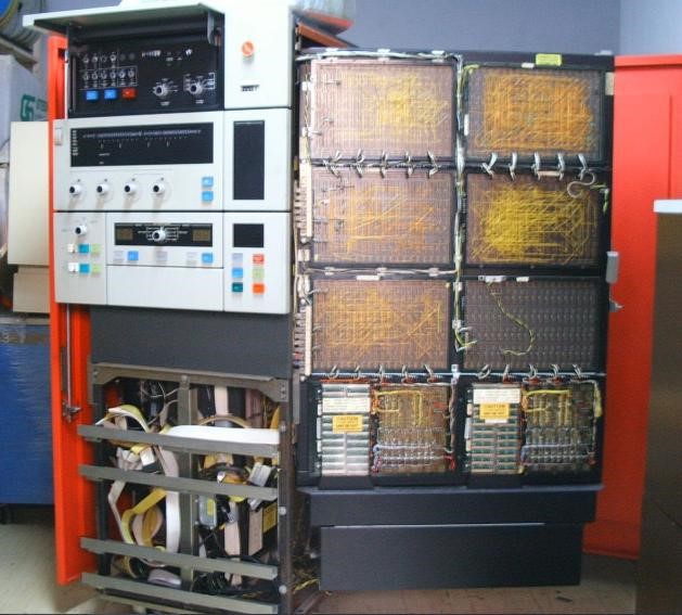
The ICL PF50John HarperFirst an explanation of the title. ICL, like many other computer manufacturers, had a habit of marketing the same (or nearly the same) processor under different names. The processor known as “Project File 50” (hence PF50) during its development came to market as the 1903A but the same machine albeit with a slower main timer was known as the 1902A. Replacing core store with semiconductor store resulted in increased performance and a re-christening to 1903S and 1902S. Further improvements brought us the 1902T, but the 1903T was derived from a different processor, the 1904S. In Resurrection 85, under the PF50 section by, Delwyn Holroyd , there was a request asking if anybody had detailed information on the PF50. I said that I had a two foot high pile of mainly A4 size manuals and documents. Bill Gallagher chose to photocopy all of these documents. These were shipped to Bill in Ireland. I believe that TNMoC paid for the shipping. Bill has now finished the mammoth task of copying. His purpose was to produce a PF50 simulator. Reports on other simulators are regularly reported in Resurrection by Delwyn Holroyd including input from Brian Spoor. During this activity It occurred to me that those who were on the original PF50 project have either died, emigrated or we have lost touch. There is one exception, but although being a very able designer he was less involved in field and sales activities; so it seems to me that if I don’t write something now all records would be lost. As I was involved over a long period what follows are my personal observations. PF50 the main central processor changed very little during the life of about 1,000 units. The changes were confined to the main timing board and the terminating of certain signals into extra, more convenient sockets. The lead up to my first involvement with PF50 was a short period in field, supporting 1902 and 1903 machines in the Oxford area. I then transferred to ICT central support and I was asked with others to join the PF50 commissioning team in Stevenage. Before I did this, I had been on training courses for 1900 peripherals including printers, card input and output and EDS8 discs and controller. The design and prototype machine production was approaching completion when I first became involved. For a few weeks I and other ICT central support staff went off with a representative from the field engineering training unit to understand the details of the machine. We then moved to the Stevenage PF50 commissioning area. This involved various tests and if something did not function as intended, we worked with designers to produce a modification and see it recorded in the design department. Commissioning went well and the machines were ready for transfer to production which was to be in the Letchworth factory. The training school representative went away to produce a training course, working with us and the designers. One of the prototypes had the wrong Plessey core store and this machine was donated to the Science Museum where it was on display for many years. Another went to the training school. And I believe two went to our in-house ‘bureaus’. IFIP 68 was where we launched the PF50 as a 1903A: this was very soon after the merger of ICT and English Electric. The launch was held at the IFIP 68 congress in the old potato market in Edinburgh near to Waverley railway station. Before the merger the two companies had planned their own large stands but in the time before the opening, the two stands were brought together in one large oval stand. We had rehearsals of the full configuration in Stevenage before shipping to Edinburgh. We all had to attend a ‘pep talk’ meeting in a London theatre by the managing director and other senior managers. With colleagues that were senior peripheral support engineers we met the hardware on the Edinburgh stand. Initially all went well but then we had serious reliability problems, not to the 1903A processor but to the EDS8 disc controller. I, with help from the Edinburgh ICT/ICL support engineers. could not track down the intermittent fault. As with many intermittent faults the controller would work for some time and then crash. After starting the controller would work OK but then fail after a period of running. We worked through the night but early next morning a Senior ICL Director came to see how we were getting on. He was very upset that Manufacturing had shipped an unreliable disc controller. He immediately took action, getting people out of bed to ship, by air, a replacement unit. One thing I do remember has that many of us got blue paint on us because manufacturing had painted over ICT on the transport covers. After that the 1903A and the full configuration worked without a single problem.
One of my early installations was an early 1902A in South London. It had never been reliable during on-site commissioning and I was called to investigate. After quite a long and difficult time trying to track down the fault I found a glitch on the timer board. At that time the only difference between the 1902A and the 1903A was the main timer. I managed to get my boss to come down to South London on a Sunday. After hearing my report and witnessing the problem he condemned the 1902A timer board: not just this one but all those previously delivered. He replaced it with the 1903A timer but with a simple feature to slug the performance. I must have impressed him because he invited me to join the Stevenage design team but not until the initial batch of about ten machines had been successfully installed. I returned to central field support to install the early customers’ machines in UK and Europe. One project from which a lot was learnt was for an on-line real time system by Mullard, under a contract from the Co-op located on a site not far from Gatwick. This system was to drive an automated warehouse. At that time this was a new venture – some of the circuits in PF50 were to enable high level interrupts in real time. It also involved additions to the E3RM Executive. I was accompanied by a colleague who normally dealt with field executive problems to operate in Executive Mode. This was to allow control of a rather unique peripheral. The section below in italics is taken from Virgilio Pasquali’s website. For much more detail go to www.ict1900.com. The special (the only one ever made) was a warehouse control unit, which totally controlled the picking of CWS food supplies from the custom-built racking system to be loaded in large mobile trolleys for despatch to CWS retail shops. A very special feature for this 3A was the Priority Interrupt Feature which supported certain customer software. It was designed and built in Crawley (I can’t remember name of company) where I spent some time with the 3A during development. ICL took on the servicing of the unit. The warehouse was designed to supply the smaller CWS stores and with the introduction of supermarkets it became redundant. What a store needed one day was delivered the next day. I think the 1903A actually drove some sort of pecking mechanism that shoved things off shelves into a trolley, thence to the lorry. The PF50 did exactly what is was claimed to do but the project did not reach fruition for a reason outside ICL’s control. Stores The first was the in-house core store later replaced with the 2½D Plessey, then the MOS. Something faster was needed but the in-house development ran into problems. I seem to recall inadequate cooling was a problem. For whatever reasons, the Plessey 2½D was chosen. I quote from the original Plessey document:- The construction of the 2½D stack is such that each wire threads more cores than in conventional memories thereby reducing the number of soldered joints to approximately half those contained in a comparable sized 3D stack. To the best of my knowledge we only had one go faulty. This was in Stuttgart where I took a replacement module with me. It took only minutes to replace the unit and the customer was back in business. Somebody local could have made this replacement but we were not to know that from the limited information given. The customer was very keen on a quick repair and he was satisfied with our efforts. First MOS store – used Intel 1K 1103 chips. It was first introduced in July 1976. 64K could be installed in the original cabinet. Enhancements were in a second cabinet giving 98K or 128K . These sizes are twice that available with core store. The development started with a test rig where I had the honour of having the task of commissioning it. Initially the 1103 was unreliable at the commissioning stage but timing modification suggested by Intel made the outcome fairly reliable. With Hamming correction already being a feature of PF50 the MOS store was completely reliable. I still claim that we were the first UK team to develop MOS store but West Gorton also makes the same claim and without precise dates we have no way of settling this. SEU (Store extension unit) The SEU enabled up to four core or Plessey store modules of 16K or 32K to be connected. This unit allowed up to three extra stores to be attached. These extra stores were mounted in additional matching cabinets that stood alongside and butted up to the main PF50 cabinet. A small number of cards selected which store was to be accessed. If a volatile store like the MOS was to be accessed during the bootstrap function a small additional non-volatile store was needed. This was not necessary when core stores were fitted because they retained information during the ‘off to restart’ cycles. IDC-Integrated Disc Controller I was trusted be the only designer of this with the title Logic Designer. I was the only one doing this but I had the full support of the design automation unit, the drawing office, the prototype manufacture department, the physical design department and the involvement of creating the necessary drivers in the executive E3RM. It was decided that the new feature should be able to drive EDS8 from the earlier 1900, the EDS30/60 from the 2812 PF56 free-standing disc control processor and the TEDS (Twin EDS) from the 1901A. This was the only disc type at the time with the capability being achieved by selecting the appropriate driver cards and executive module. Before starting the design, I had to study all three disc controllers to make sure that the new design accurately mirrored the previous controllers. The 2812 was easy because I had been trained on this and had serviced a few earlier. The TEDS implementation was fairly easy because the 1901A was being commissioned alongside the first PF50 so I was able pick up what that team were doing. The EDS30/60 controller based on the PF56 was more time-consuming because whilst studying it, a partial redesign of some of the functions could be achieved. Sectors being written or read from the disc needed a parity check. The PF56 hardware created or read the check bit employing a parallel method. I found that this could be done serially with a considerable hardware saving. Disc drives – One other thing that I discovered was that the PF56 had a ‘flywheel’ board to clean up the signals coming off the disc circuits. Checking the actual drive specification, I found that the disc drives that we were supporting had this already built in. Hence the one in a controller was superfluous so further reducing the cost. The development of this IDC was to save on hardware and this included not having the whole PF56. Having established a sale price for the PF56-based EDS30/60 system, ICL could maintain the same sale price with a considerably lower manufacturing cost. Customers needed less space and air conditioning. This cost reduction was simple because the PF50 had the necessary signals available for connection. There was a power supply unit that could supply the necessary currents and space available inside the main cabinet. To fit an IDC the readily available signals had be terminated in a plug and socket power connection cables produced and extra fixing holes made in the frame for hinges. Early machines were easily retrofitted to the IDC in the field but all subsequent machines had the necessary connections built in as standard. Also the correct executive had to be supplied when this feature was fitted. I don’t have production figures but many of the last two or three years of PF50 production were sold with this feature fitted: at a guess about 600. So the profit that the company made was greatly helped by this feature being available. PAC (Peripheral Access Controller) This unit allowed up to eight additional 1900 Standard interfaces, two of which were available with the F=1 faster interface selectable. F=1 capability allowed fast data transfer in 24bits rather than the standard six bits. Many West Gorton machines had this as standard. The unit was fitted into main cabinet but not at the same time as the Integrated Disc Controller. In the later part of the sales period, the PF50 machines were painted in New Range colours. The configuration at that time was with MOS store and the Integrated Disc Controller. It was a very neat package with deliveries continuing well into the life of 2903. The first PF50 was delivered in 1968 and it sold for about four years. |
The English Electric KDF 6Andrew HerbertDuring the summer of 2018 I was contacted by Mrs Tina King who wished to donate her late father’s collection of computing memorabilia dating from the time he worked at National and Grindlay’s Bank setting up their first computerised systems on an English Electric KDF 6 1 computer. Mrs King and her husband kindly came to my house to deliver a KDF 6 operator’s console, some circuit cards and a bundle of documents for me to take across for accession to the museum’s collection.
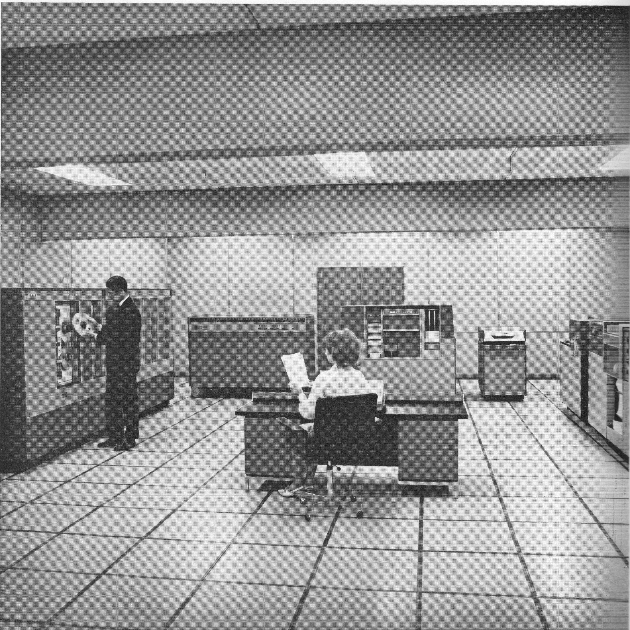
I was unaware that English Electric had produced a KDF 6, and searching the Web produced very little information about this machine. There are passing references to the KDF 6 in several books on the early (British) computer industry, such as Lavington’s Early British Computers but they give little information other than it was a commercial data processing machine, derived from an earlier KDN 2 process control machine and developed into later KDF 7 and KDF 8 machines. These texts all agree that about 12 or so KDF 6s were sold and they cost about &60,000 – the machine was priced to compete with electromechanical punched card machines used in banking and allied industries. There is an entry for the KDF 6 in The 1968/9 European Computer Users Handbook which reveals some technical detail. Perhaps more fun is a video in the Getty Archive which shows a KDF 6 in the studio for ITN’s coverage of the UK 1966 general election processing results, and as its party piece playing Land of Hope and Glory through a loudspeaker ( www.computerconservationsociety.org/rd/kdf6spr.htm ). Further searching reveals that writing an Algol 60 system for the KDF 6 was one of the first projects undertaken by Computer Analysts and Programmers (CAP) Ltd (referred to in a paper Crisis, What Crisis? CAP also wrote an Algol 60 system for the Elliott 900 series of minicomputers , and the source code of the Elliott system shows this version was strongly influenced by the KDF 9 Whetstone Algol system written by Randell and Russell, so perhaps the KDF 6 Algol 60 system was taken from Whetstone to Elliott 900 via KDF 6? 1. Most authors write English Electric machine names as a single word, but the company’s brochures and documents describing the machine always write the digit separated by a space as in KDF 6 rather than KDF6. Alongside these sources, the web turns up an advertisement for a KDF 6 in New Scientist ( www.computerconservationsociety.org/rd/kdf6.htm ), and Grindlay’s advertising a Research Fellowship “to investigate new methods of applying computer science to banking problems”. The advertisement promises full access to Grindlay’s KDF 6 and offers an impressive salary of £1,300-£1,500 per annum. Alongside these I found a former KDF 6 programmer’s blog which yielded the following image of a KDF6 from an sales brochure ( www.computerconservationsociety.org/rd/kdf6br.htm ) and a paper Megabytes for metals: development of computer applications in the iron and steel industry, in The Journal Ironmaking and Steelmaking, which gives an account of the use of KDF 6 machines by Parkgate Iron and Steel of Rotherham both for real-time control of steel rolling mills and for commercial applications. The article reports: “the KDN/KDF machines are good fast processors with mnemonic code software that was easy to understand and implement.” The KDF 6 at Grindlays Mrs King’s father, Harry Marsh, worked at National and Grindlays Bank (now ANZ Bank) from 1960 to 1976. In 1963 he was selected as a member of the Bank’s first computer team and assisted with the installation of the KDF 6 system and programming applications for it. The machine was the first KDF 6 delivered and was handed over to Grindlays on 30th December 1963. Prior to the handover a team of Grindlays staff had been located at English Electric’s premises using an in-house KDF 6 to develop the initial applications. English Electric provided one of its own staff who had a banking background to teach the Grindlay’s team systems analysis and programming. In addition, some of the Grindlay’s staff took evening and university classes in computer science as preparation – Mr Marsh’s archive includes University of London notes on how to program an imaginary computer called IMDAC (imaginary digital automatic computer) and on logical design of computing circuits.
After undertaking systems and programming work for a couple of years, Mr Marsh was appointed as Computer Operations Manager and took the machine from single shift to 24-hour operation. In 1972 the bank’s general ledger was computerised, but this required 30 hours of data processing time, 5 days a week so additional time was purchased from the only other remaining KDF 6, owned by Equitable Life, who had premises nearby. In 1974 ICL, which by then had taken over English Electric computers, announced it could no longer economically provide maintenance for the KDF 6 after December of that year as it had just two engineers qualified to do so. So, the decision was taken to replace the KDF 6 with an IBM 370/135. But the KDF 6 had to be kept running until the IBM was ready and software transferred. It was hoped ICL might continue maintenance beyond the end of the year. By October 1974 the KDF 6 was very fragile – the bank dared not turn it off for fear it would never restart and then in December the air conditioning in the computer room failed irreparably. Disaster! Holes were knocked in walls, portable cooling units brought in, a kettle kept boiling permanently generating steam and cabinet doors removed all to keep the KDF 6 going. It survived until December and the IBM team rushed to move over applications in a much more compressed timescale than originally planned. The switch over finally happened on 16th December. Quite a cliffhanger! (This account comes from the Winter 1963 edition of Monsoon the National and Grindlays magazine and from the March 1975 edition of Forum, the newsletter for the staff of Grindlays Bank in Britain.) There was obviously some tension between the computer staff and the bank’s more traditional clerks. The Summer and Autumn 1964 editions of Monsoon carries a series of letters about years in which 29th February would fall on a Saturday. The computer staff wrote a program and produced a table. One of the banking staff gleefully pointed out he had omitted the rule for centennial years not divisible by 400, and that had calculated a corrected table by hand much more quickly than they had coded their program! The KDF 6 System and Software
The documents handed over by Mrs King include a number of English Electric brochures, probably dating to the original purchase in 1963. Banking and KDF 6 introduced the machine and offers an example configuration and work schedule for a bank holding 20,000 accounts – one KDF 6, 4 magnetic tape decks (33,000 ch/s), one magnetic tape switch unit, one 600/900 lines per minute lineprinter and one 1,000 ch/s paper tape reader. It further explains that the magnetic tape switch unit allows offline printing of data from magnetic tape – the unit can be set up with up to 25 templates for pulling data off tape and laying it out on customised stationery. A more colourful English Electric KDF 6 Office Data Processing System brochure gives a little more detail – mentioning the KDF 6 logical circuitry is based on the same “plug in element design using the latest incorporating the latest electronic techniques” used by KDF 9 and KDP 10. The main store consists of 24K 18-bit words, which can be divided into three 6 bit characters called “triads”. The peripherals are all compatible with the KDF 9 and KDP 10, and from the brochure can be seen to be painted in the same maroon and sky-blue speckled paint scheme as I recall from the KDF 9 I used at Leeds in 1972-5. The paper tape reader operates at 1,000 ch/s and can stop from full speed without over running the next character. The monitor typewriter is a Friden Flexowriter. A 110 ch/s paper tape punch is offered and from the photographs looks to be a typical TeleType Corporation BPRE punch unit as found on many British machines. The line printer operates at 900 lines per minute for numerical data, 600 lines per minute for alphabetic data. The symbol set comprises capital letters, decimal digits and 18 punctuation marks and symbols – ,;:.'"*-()/&%#+=@. A maximum of four magnetic tape decks can be connected. Notably not described are card readers, disc drives or graph plotters, which were available for the KDF 9, although the KDF 6 Programming manual does mention the availability of a punched card reader. The brochure also mentions three programming systems. The first is “a new programming language called TALK”, in which programs are written as “clear, meaningful English statements”. No examples are given, but the description suggests a COBOL-like structure with separate data and procedure descriptions. Procedure descriptions could contain imperative statements such as MULTIPLY and conditional statements such as IF or UNLESS. In addition there was a KDF 6 “User Code” – for “direct programming”, i.e., an assembler with relative and symbolic addressing, comments, etc. At a lower level there is provision for “Machine Code” – a purely octal notation. Other software mentioned includes a library of standard procedures for sorting, sterling and decimal conversion, control of peripheral devices, sorting and data manipulation. The KDF 6 Instruction Set The brochure KDF 6 Programming gives us some detail of the KDF 6 instruction code. The machine had a main store of 24K 18-bit words and four registers named A, B, C, D. A and B can be concatenated as an extended register called X. A word could be interpreted as an integer, or as three six bit characters (“triads”). In machine code an order was represented by two octal digits (six bits – allowing for 32 instruction codes) for the function code and four octal digits addressing an operand in main store (12 bits – allowing for 4096 locations). The instruction set was quite basic:
This is a relatively similar instruction set to the Elliott 920A, a contemporary 18-bit transistor logic minicomputer, with the added benefit of four accumulators rather than just one. In comparison to the extensive KDF 9 instruction set with floating point facilities, subroutine jump nesting store, index registers etc., KDF 6 is quite primitive. Note the absence of any form of subroutine entry/exit instruction, but the mention of standard libraries for input/output suggests a standard entry sequence, perhaps based on loading return address into a register, jumping to the routine, which stores the return address and exit via a modified jump? The instruction times are surprisingly slow:
By comparison a simple load instruction on a 920A is around 27µs. Could it be the KDF 6 was a serial rather parallel CPU? The manual is not explicit about addressing, although the term “core module” appears from time to time in the documents but is undefined. It could be that operand addressing is absolute in the range 0-4095, relying on MOP/MOM instructions to access higher regions of store, or possibly relative to the module in which the program is executing (as with the Elliott 920B and successors). Input/output to slow devices is directly through registers, character by character. For fast devices, block transfers can be set up from buffers in the second core module and program execution will continue in parallel with data transfer. Only one block transfer may be in process at the time and there are no facilities for multi-programming (i.e., interrupts). The block transfer facility is provided by library subroutines and the KDF 6 User Code provides special mnemonics to set up calls to these routines. There is a vestigial summary of KDF 6 User Code in the programming notes. Function codes can be written in octal, or as the mnemonics given earlier. The operand field can be:
“Data areas: any triad in a data area may be addressed by a symbolic address followed consisting of a minuscule followed by a decimal number. Data areas must be defined by directives at the beginning of the program2. ” 2.This feature of User Code is an enigma: there does not appear to be a machine level means to address by triad. Labels can be:
Unfortunately, there are no examples to reveal the syntax of each label type. Summary The English Electric KDF 6 was a small business minicomputer derived from the larger KDF 9 and KDP 10 computers, giving it the benefit of a mainframe quality tape reader, line printer and magnetic tape system. It had a reasonably large memory (24K) for a machine of its type and a useful instruction set. It had a slow processor, but given its workload was likely to be input-output dominated this was probably acceptable. It came with an assembler (User Code) and a business-oriented programming language (TALK). In addition, there was an Algol 60 system developed by CAP. The first KDF 6 was delivered to National and Grindlay’s Bank in 1963 and served the bank until its replacement by an IBM 370/135 at the end of 1974. Very little information about the KDF 6 seems to have survived but The National Museum of Computing is fortunate to have an operators’ console, some circuit cards and documentation, donated by Mrs Tina King, in memory of her father, Harry Marsh. Andrew Herbert is a leading member of the Society, Chair of The National Museum of Computing and leader of the EDSAC Replica Project. He can be contacted at andrew@herbertfamily.org.uk . |
Book Review: Charles & Ada : The Computer’s most Passionate Partnership
Dik Leatherdale|
From the title you might be forgiven for thinking that this tome is suggestive of a romance (as we might now describe it) between Charles Babbage and Ada Lovelace – both seminal figures in the pre-history of computing. And you might be surprised to find that they don’t actually meet until half way into the book. So, the first half is a good account of their lives up to 1833. Understandably the emphasis is on Babbage since he was then aged 41 to her 17. Babbage comes across as a more interesting person than I had expected with an enthusiasm for all sorts of machinery and industry which seems vaguely reminiscent of Samuel Smiles and Adam Smith. But even here we are presented with a rather rude and egocentric person, failings which seem to increase with his advancing years and with damaging consequences. James Essinger is scrupulous in distinguishing confirmed fact from speculation. Phrases such as “it is impossible to know...”, the less emphatic “... we don’t know for certain” or the more positive “Surely...” give us due warning. In the second half of the book such qualifications seem to increase in frequency as the author weaves his narrative around the progress (or rather, the lack of progress) of Babbage’s machines and his supposition of some sort of intimate relationship between the pair which is frankly unsupported by little more solid than the light-hearted tone some of the correspondence between them. Consider though that, in Babbage’s autobiography Lovelace merits but a single mention – mean-spirited when seen through our eyes. The author speculates that Lovelace’s idea, so central to our craft today, that the Analytical Engine was capable of more than mere numerical calculation, was either not understood by Babbage, or was dismissed as unimportant. Here surely, Essinger has a point. Babbage was notorious for failing to produce any actual machines. Every time he pushed his art forward, he seems to have conjured up a better idea and abandoned his earlier thoughts. In more recent times, Turing’s sojourn in Teddington designing the ACE computer suffered the same lack of progress for the same reason until he decamped to Manchester. Perhaps we should not judge Babbage too harshly. This book has considerable merit and is obviously the product of extensive and careful research but is let down by its romantic pretensions. Maybe the publishers encouraged this slant. But we don’t know for certain. |
The Flexipede Revisited
Kate Sullivan, David Duce, Bob Hopgood
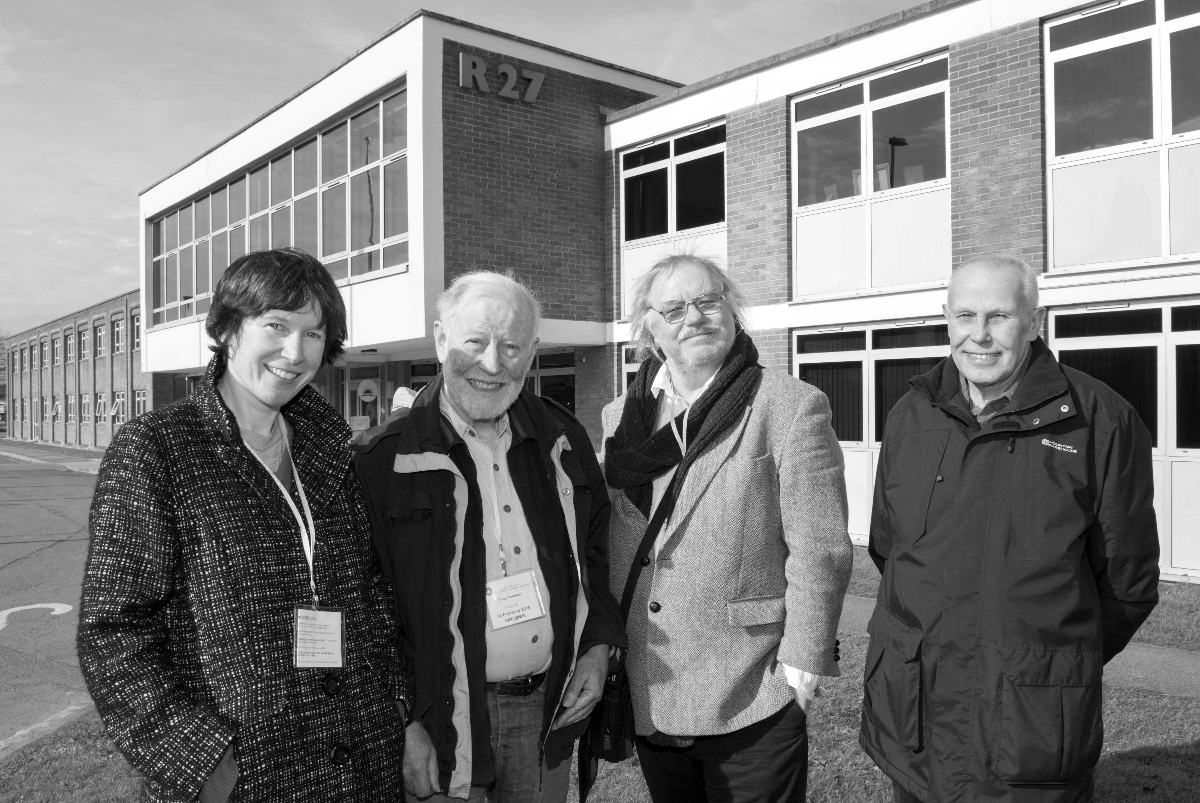
Tony Pritchett created The Flexipede in 1967, probably the first known character computer animation telling a story worldwide, certainly in the UK. And it had a soundtrack. Sadly Tony Pritchett died on the 28th August 2017.
Animator and filmmaker Kate Sullivan was a friend of Tony’s. She is currently creating a multimedia project which documents his work. The pair were working on the project together. Kate is providing a temporary home for Tony’s archive. The collection includes all sorts of fascinating materials relating to his animation career (1967 - 1982). Items include the original 16mm master negative of The Flexipede along with film footage and printed materials relating to a wide range of projects (Ridley Scott’s ‘Alien’, ‘Blade Runner’ and the very first Channel 4 logo to name but a few.) Kate is very keen to hear from anyone who would like to contribute to the project, which is currently in progress. It is centred upon Tony’s career, but by extension documents the work of his colleagues and the formative years of the British computer animation industry. All contributions would be very much appreciated. No contribution is either too anecdotal or technical! If you would like to get in touch or simply find out more about the project-in-progress, please visit its (regularly-updated) home: www.Tonypritchett.co.uk.
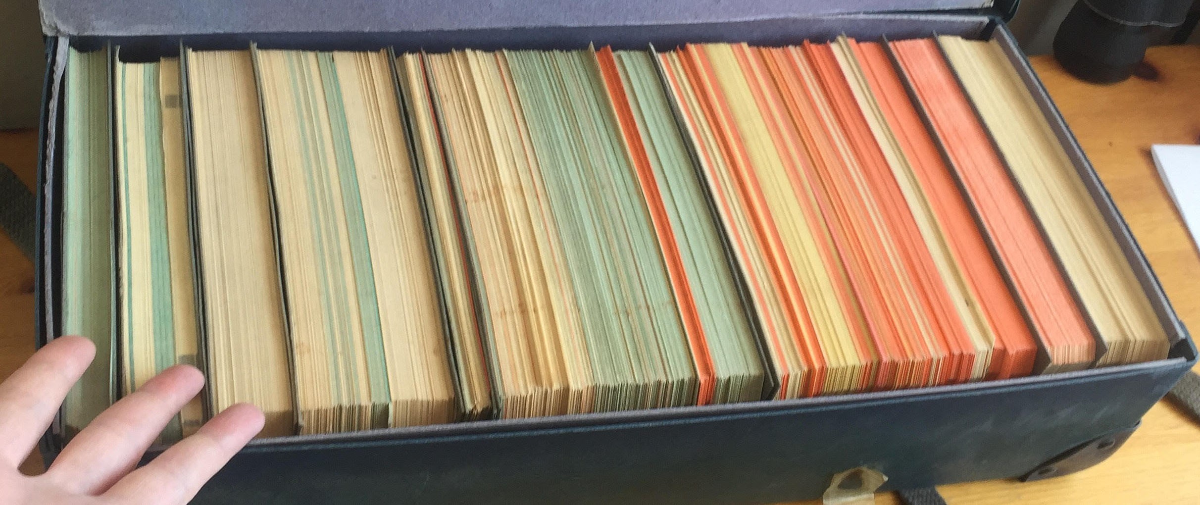
Back in the archive – Kate mentioned to Victoria Marshall that amongst Tony’s possessions was a 2000-card drawer of computer punched-cards cards which, according to Tony, included his Flexipede program. Would it be possible to recreate The Flexipede 50 years after it was written? Flexipede Card Box
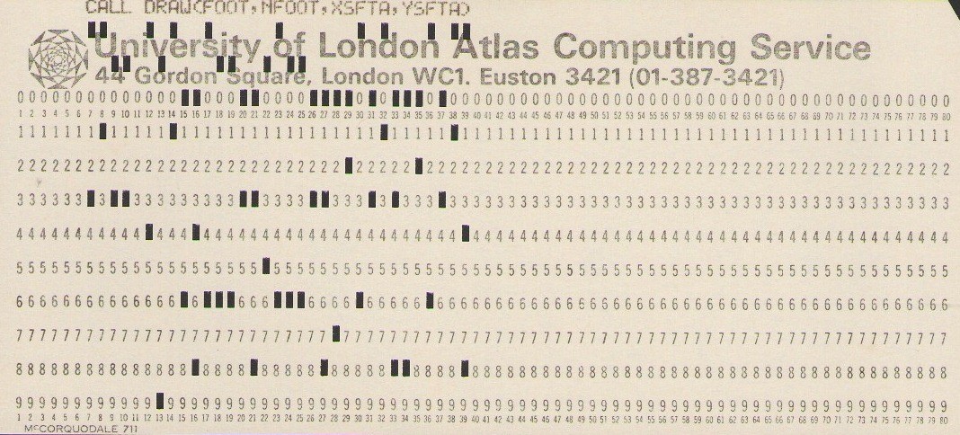
The card box included several card decks destined for the London Atlas Computing Service. Most cards had printing across the top, rather faded at times. Some had no printing. It was then necessary to read the hole punching.
An early deck that we looked at appeared to be Flexipede but it was an earlier version. Kate has some experimental 16mm footage containing this version. Other decks were from other animation projects. The Flexipede Program Eventually, a card deck was found that looked correct. It was generating an IBM-compatible ½” magnetic tape for the Benson-Lehner 120 (BL120) Microfilm Recorder at Culham Laboratory (where Tony Pritchett said the film was produced). In the 1960s, the sensible way to generate computer animation was to use a microfilm recorder. A Stromberg-Carlson 4020 (SC4020) microfilm recorder was installed at AWRE Aldermaston in 1963 and was also used by Harwell for displaying nuclear simulations on hardcopy paper or 16mm/35mm film. In 1965 thermonuclear research moved from Harwell to Culham, who purchased a BL120 microfilm recorder (compatible with the SC4020). The BL120 was a faster cheaper second-generation alternative that could process all SC4020 magnetic tapes. Kate Sullivan took on the mammoth job of photographing the box of cards, three cards per photograph. Bob Hopgood typed in the contents (making quite a few errors in the process) and David Duce produced a Java program that performed as close to the Fortran program as possible generating frames of SVG graphics that could be displayed approaching 24 frames per second to simulate the BL120 output. This uncovered quite a few errors in the card transcriptions that needed to be addressed. Only two cards of the deck were missing and we were able to deduce these to arrive at a complete listing of the card deck. Four subroutines were not found called IDST, IDEND, ADVFLM and VECTOR. It turned out that these were provided as BAS cards, the Atlas object code on binary punched cards. Later, Kate found in her archive confirmation that Tony had made visits to Aldermaston, Culham and Chilton to see if he could get access to the Culham BL120 or the Aldermaston SC4020 and was offered access to the BL120. Paul Nelson at Chilton offered him Harwell’s Fortran (Hartran) version of the basic SC4020 SCORS code for generating ½” magnetic tapes for either the BL120 or the SC4020. Tony used these as the basis of a rewrite in London’s Fortran V. The result was the BAS subroutines IDST, IDEND, ADVFLM and VECTOR which Tony used on a number of projects. To give some idea of the code, Woody Anderson did a similar recoding for the IBM 360 which he published in the UAIDE Proceedings for 1970. Tony’s Fortran deck included a large set of data cards giving all the positions of the flexipede legs. An earlier program must have pre-calculated these to save time in short development runs. Approach The ultimate goal was a Scalable Vector Graphics (SVG) definition of The Flexipede using either Javascript or SVG’s declarative animation that was as close to the original as possible. The ability to repeat an animation cycle via the repeatCount attribute in SVG would greatly reduce the size of the completed SVG document. To understand the Flexipede program itself, the decision was made for David Duce to reprogram it in Java and for Bob Hopgood to focus on generating an animation that used the full power of SVG. Although the Flexipede Program is not overly long, some of the code around the algorithms used was worth reprogramming to ensure correctness. The titles at the beginning and end were not part of the Flexipede Fortran program. Tony had mentioned to Kate that he had done these using Letraset and Kate found the original Letraset artwork in the archive and was able to produce a good rendering of these. The existing sound track needed some filtering to make it sound more like the original. Paul Hopgood obliged. The graphics package used was unknown initially but eventually it was clear that it was a low level set of routines that just took coordinates defined on the 1023 by 1023 grid of the microfilm recorder and output vectors given the start and end positions. The Java Approach The aim here was to answer the question Is it feasible that the Fortran we have was used to create The Flexipede animation? The Fortran used had some unusual features. DO loops could have alphabetic labels. There was an Algol-like block structure with BEGIN and END statements and the Fortran subroutines could be nested (three END statements in a row was certainly unexpected). Some variables were passed through subroutine arguments, others were shared, but did not use COMMON blocks. Later, a Fortran V manual (dated May 1967) came to light in Tony’s archive which described these Fortran extensions so we are confident this is the Fortran dialect used. The aim of the Java translation was then to generate a frame-based animation from output similar to that produced by the original program. The four subroutines IDST, IDEND, ADVFLM and VECTOR defined in BAS code were replaced by code that recorded the routine invocations and argument values in a trace file. IDST and IDEND were microfilm recorder initialisation and termination routines that could largely be ignored. ADVFLM(1) advanced the film one frame. VECTOR drew a vector from (XS, YS)0000 to (XF, YF) in the 1024 by 1024 coordinate system. Debugging via a trace file helped us understand how the program worked. The trace file was then converted to Scalable Vector Graphics (SVG) line drawing elements for display. Using SVG’s visibility controls, we could run through the frames, 24 per second or a frame at a time. We discovered some transcription errors in the data cards and worked out some subtle changes such as the solipede swallow. Buttons and JavaScript code were added to update the animation at 24 frames per second or to single-step one frame at a time. Reprogramming Flexipede in SVG Body Parts
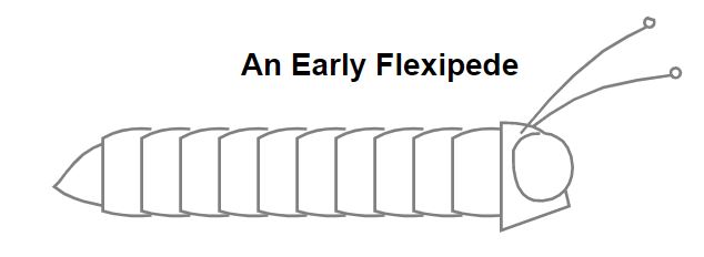
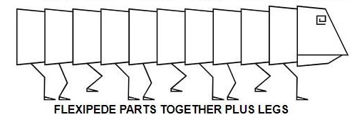
The body parts are defined by the arrays BODY, SOLIBOD, FOOT, SKULL, DJAW, EYE and PAD at the beginning of the program: The SKULL and JAW are separate so that the flexipede can open up its head to swallow the solipede. Only the first two lines of the eye are normally drawn but the full eye is drawn when the solipede passes overhead. PAD is the suction end of the flexipede’s tongue. Story Board The storyboard of the animation is quite simple where the numbers indicate the number of frames of the activity:
The flexipede and solipede sizes change on each crossing. Effectively the flexipede and solipede only travel from left to right at full size but two variables adjust the size and flip the coordinate in the X-direction about the centre so that right-to-left and left-to-right traversals at various sizes can be easily achieved. Accompanying the animation is a sound track of a flexipede that needs oiling and a sprightly bouncing solipede that Tony created. Tony told Kate that he created the film’s soundtrack recording the sound of a squeaky office chair, a garage hoist, a Jew’s harp and himself gulping using a domestic Philips reel-to-reel tape recorder belonging to the sister of his friend, Hugh ‘Ras’ Riddle. (Tony went on to create the installation Sidebands with Ras, which, along with The Flexipede, was exhibited at Cybernetic Serendipity, 1968.) Tony told Kate that the sound was sneakily recorded at night at Ras’s workplace – a basement lab in the medical electronics research department of Bart’s Hospital.
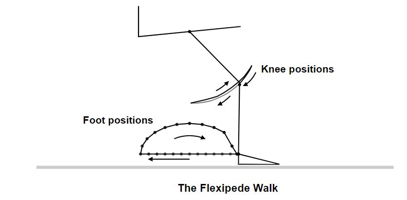
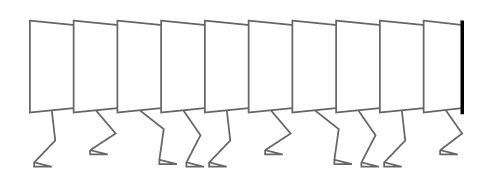
The timings for the various events defined in the program matched those in The Flexipede film except that the holds between scenes were not the same in the released film version. Our guess is that additional blank frames were inserted at some later stage, presumably to fit the soundtrack exactly to where it should be relative to the animation and titles. Flexipede Walk The Flexipede walk in the card deck is defined by a set of arrays giving the absolute positions of the 11 legs for the 24 positions of the animation cycle which are read in from data cards labelled WALK DATA. Using absolute position values somewhat obscures the fact that the leg movements are in a cycle of four (the 5th segment of the flexipede has the same leg movement as the first, the 6th the same as the second and so on). Also, the 2nd leg cycle is the same as the first but displaced by 6 places, the 3rd displaced by 12 and the 4th displaced by 18. So one leg cycle provides all the information needed to create the animation of all the legs. The path of each leg is from the top of the leg to the knee and then to the start of the foot with the same horizontal foot for each position. The 24 leg positions are shown below. The dashed lines are the starting positions from right to left of the animation of the first four legs which then get repeated for the following legs.
Going from right to left, the foot positions move backwards along the ground then come forward on the curve of a circle. The knee positions are calculated using a similar algorithm we believe to that which is used for the solipede. For each traversal of the flexipede variables are set to give its size and direction of travel. For the initial walk the legs cycle through the 24 positions as the flexipede traverses the screen over 420 frames. At 24 frames per cycle that amounts to 17.5 repeats which SVG can handle so only a single 24 loop needs to be declared but with a repeatCount attribute set to 17.5. Solipede Leap The path of the Solipede is defined by the leap trajectory which gives the Y position of the top of leg and how far the foot is off the ground for a 12-frame rather than 24-frame cycle. The solipede foot moves forward 6 units each frame of the cycle and the position of the knee is calculated from the X and Y positions of the foot and the Y-position of the top of the leg defined by the leap trajectory table. The basic motion from the leap trajectory table is shown together with a forward movement to give the leaping motion.
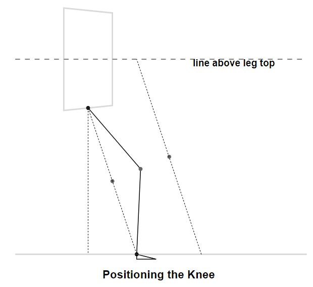
The leap program is designed to give a reasonably correct positioning for the knee in this motion. This is done by a heuristic that moves the knee up and forward depending on the distance that the foot is in front of the top of the leg. The line between the top of the leg and the foot is moved forward as though the leg was longer creating a parallel line that stops at an arbitrary line above the top of the leg. The knee is then positioned half way between the original half way point and the new one. The choice of heuristic seems to be one that Tony invented. Perhaps flexipedes and solipedes do have legs that stretch and contract. The table of positions that define the flexipede’s walk appear to be defined in a similar way. An earlier program found in the deck of cards may be an early version of the program that generated the flexipede’s leg movements.
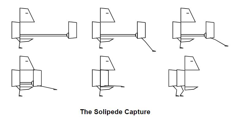
Solipede Capture The solipede capture is reasonably complicated as the solipede has to be sucked into the open jaws without the legs dangling below and then to right the legs once the capture has occurred. The array defined by: REAL PL(4,4)/50,50,90,110,66,25,120,70,69,10,136,30,70,0,140,6/
gives the intermediate coordinates of the solipede leg during capture. Once captured, the head moves forward half a body segment length and the body back by the same amount thus creating a flexipede with an extra segment that walks off satisfied. Flexipede Hits the Wall One unusual aspect of the Flexipede film was that on reaching the edge of the screen area it starts to generate a wall. Effectively the lines of the Flexipede that are greater than 1023 in the X direction or less than zero have the X-coordinate changed to either 1023 or zero creating a set of vertical lines. This overstriking gives a more intense (thicker vertical line) on the film image indicating that the Flexipede used a low level routine with no genuine clipping at the screen boundary (0 and 1023 in the X and Y directions).
The VECTOR routine in the basic SCORS library first changes all coordinates less than zero to zero and those greater than 1023 to 1023 before splitting long vectors into 64-bit segments required by the microfilm recorder. This confirmed that Tony used low-level SCORS clipping for generating the Flexipede BL120 output. An animation of The Flexipede (at www.chilton-computing.org.uk/acl/htmls/flexipede/flexipedescorsclip.htm ) shows the SCORS clip as the flexipede emeges from a wall on the left and exits via one on the right. Conclusions The big question was whether the card deck we found was the program that generated the film called The Flexipede. The Java program indicated that the program generated 1784 frames of film. Kate managed to find a Job Control card saying it was the final run and the lineprinter output giving the results of the run on the London Atlas. This was: LRF91PB1, A PRITCHETT BL120 TEST
DATE 07.10.67
TIME 14.35.27
SERIAL NUMBER 12337285
REQUESTED USED COMPILE
INSTRUCTION INTERRUPTS 96000 43353 1360
COMPILE STORE 120 89
EXECUTION STORE 50 34
DECKS BLOCKS WAITING
MAGNETIC TAPES 1 37 56
IBM MAGNETIC TAPES 1 1799
STORE TIME DRUM TIME DECK TIME
16718 10 322
COMPILER NUMBER 34
F FACTOR 18
BC 1 758
BC 2 762
INPUT 0 11 BLOCKS READER 1
INPUT 1 1 BLOCKS READER 1
INPUT 2 3 BLOCKS READER 1
OUTPUT 0 648 RECORDS LINE PRINTER
OUTPUT 13 32 RECORDS ANY
The run was made on 7th October 1967, ran for 4 minutes and 31 seconds (of which 8.5 secs were for compilation). The main output was 1799 blocks of ½” magnetic tape. Magnetic tape blocks destined for the SC4020 and BL120 had a maximum of 512 instructions. New frames took place each advance film. Looking at the amount of instructions required for each flexipede frame this was well within the 512 instruction limit for all but the most complex scene. The tongue is the main drawing that needs vectors greater than 64 units long. Tapes destined for the BL120 had header and footer frames added to identify whose output it was. In consequence, the flexipede program generating 1784 film frames would require a few more than 1784 blocks of ½” tape so 1799 blocks produced is pretty well exactly what you would expect for a complete run of the Flexipede card deck. The evidence is not conclusive but leads us to believe that Kate does have the card deck that generated the film The original and re-creation are at www.chilton-computing.org.uk/acl/htmls/flexipede/TheFlexipede.mp4 and www.chilton-computing.org.uk/acl/htmls/flexipede/fulljavaflexipede.htm . Some of the manuals that Tony had related to his use of the Culham BL120 microfilm recorder from the London Atlas are available at the Chilton website. A longer version of this paper which includes the Flexipede code, the small animations and the links to the various Flexipede animations described above and relevant 1967 manuals can be found at www.chilton-computing.org.uk/acl/htmls/flexipede/flexipede.htm . Acknowledgements We would like to thank Paul Hopgood for getting rid of the worst of the background noise on the soundtrack and increasing it to a meaningful volume. Also Victoria Marshall at Chilton who made us aware of the possibilities, provided a home for online copies of the relevant manuals etc, and gave many useful comments on the paper. |
50 Years ago .... From the Pages of Computer WeeklyBrian AldousNDPS to expand its LEO strength: To provide extra computing power to meet growing processing demands without the need for extensive reprogramming, the Post Office is installing five LEO 326s, ordered from ICL. The five machines, worth over &2 million, have been produced on specially re-opened production lines at ICL’s plant at Kidsgrove, Staffs. (CW 12/3/70 p32) 1904As to aid BR’s Payroll Centralisation: As part of the British Railways Board computerisation process, two ICL I904As are to be added to the present 1906s installed at Crewe and Peterborough. The two machines are worth about &1 million and their main use will be for a centralised payroll scheme for 350,000 employees. (CW 19/3/70 p11) Three Mod Ones for MEDIATOR: An order for hardware which includes three Modular One Processors has been received by Computer Technology from Plessey Radar for installation in the London Air Traffic Control Centre at West Drayton. The computers will process data from the long-range radar station newly opened at Burrington in Devon, which forms part of Mediator, the Board of Trade’s en-route air traffic control system which covers the southern half of the UK. (CW 26/3/70 p40) SRL given contract to install 503 in Moscow: A contract to install an Elliott 503 in Moscow has been given by ICL to Systems Reliability Ltd of Luton. There is already a 503 in Moscow and expansion of existing applications will be achieved by the installation of a similar system. The equipment to be installed includes the 503, which has 64K 40-bit words of core, a printer, four magnetic tape drives, and a card reader. The 503 supplied by ICL, which was originally an Elliott internal order, is unused and was the last one off the production line. (CW2/4/70 p1)
4/70 link with March for ICI Research Lab: The central instruments research laboratory of ICI at Pangbourne, which is in the forefront of research in process control, will take delivery this year of a system consisting of an ICL 4/70 linked to a March 2140. This major installation, which is likely to lead to the development of new high-level process control languages, is a significant order for ICL and for GEC-Elliott Process Automation who will provide the 2140 system. This is the first ICI order for a System 4 machine, but it is believed that it took delivery of a 2140 for on-line control of a mass spectrometer late last year. (CW 9/4/70 p32) Mod One to be front-end processor on UKAEA 4/70: An advanced interactive graphics display system is to be built by the Culham Laboratory, UKAEA, using a Modular One computer from Computer Technology Ltd as a front-end communications processor on their ICL 4/70 system. The software will be written at Culham in association with CTL. The communications system will be one of the first in which a front-end processor has been attached to an ICL 4/70. In addition to the graphics terminal, a Cossor CSD 1000 display, the system will have initially about 64 teletypewriter terminals and eight alphanumeric CRT displays. (CW 30/4/70 p1) Michelin orders Dual PDP-8/L Online System: A &70,000 order for a dual on-line computer system for the Michelin Tyre Co is announced by Instem Ltd of Stone, Staffs. The system, which contains two Digital Equipment Co PDP-8/L processors, will control delivery of materials and process sequences in a new tyre plant now being built by Michelin at Stoke-on-Trent. Instem will design, assemble, and program the system which will be operational later this year. It is believed to be one of the first applications of on-line computers in the UK rubber industry. (CW 30/4/70 p27) Ferranti System Checks Cross-Channel Traffic: With cross-channel traffic through the Dover Car Ferry Terminal expected to increase over the next few years to a million vehicles and six million passengers annually, the Dover Harbour Authority has opened a &2 million terminal extension incorporating an 8K Ferranti Argus 400 computer-based Digi-TV system to monitor traffic, confirm and allocate ferry space, provide communication control and produce sailing manifests. Catering for 600 vehicles an hour on 48 ferries and 48 hovercraft operating daily, the system uses the computer’s word block store coupled to a Digi-TV controller feeding 16 TV screens and an illuminated display board. Computer communication is via a keyboard operated by control personnel, and traffic control is carried out with a Pye closed-circuit monitoring system and UHF pocket-phones as well as a Reliance 150-line private automatic telephone exchange. (CW 7/5/70 p28) Mod Ones ordered for pathology and worms: Two orders for Modular One systems for work in the medical field have been announced by Computer Technology Ltd. One machine will be used for the development of a pathology laboratory system, and the other will be used for the study of the nervous system of a worm. The pathology laboratory project will be developed jointly by CTL, Dundee University, and the Scottish Home and Health Department on a system installed at the university’s department of clinical chemistry at the Royal Infirmary, Dundee. The installation, which will initially be used in routine clinical chemistry analysis, is regarded as a first step towards a central computing facility for several laboratories within a hospital complex, and additionally for remote users via GPO lines. (CW 14/5/70 p32) Long-awaited multiple disc launched by ICL: More than 18 months after the first order was reported ICL has officially announced its multiple exchangeable discs store for use with both the 1900 and System 4 series of computers. To be known as the EDS 30, the system uses 20-surface disc packs and can have from three to nine drives. Full software support is being provided. The first EDS 30 is scheduled to go to Schweppes which placed that first order in 1968 when plans to replace a KDF8 with IBM equipment were switched to an ICL 4/50. This is due to be installed this month. (CW 28/5/70 p1)
|
Forthcoming EventsLondon Seminar Programme
London meetings take place at the new BCS location – 25 Copthall Avenue Moorgate EC2R 7BP starting at 14:30. The venue is on the corner of Copthall Avenue and London Wall, a three minute walk from Moorgate Station and five from Bank. You are strongly advised to use the BCS event booking service to reserve a place at CCS London seminars. Web links can be found at www.computerconservationsociety.org/lecture.htm . For queries about London meetings please contact Roger Johnson at r.johnson@bcs.org.uk. Manchester Seminar Programme
North West Group meetings take place take place in the Business School of Manchester Metropolitan University Chester Street, Manchester, M1 5GD: 17:00 for 17:30. For queries about Manchester meetings please contact Alan Pickwick at alan_c_pickwick@btinternet.com Details are subject to change. Members wishing to attend any meeting are advised to check the events page on the Society website at www.computerconservationsociety.org/lecture.htm. MuseumsSIM : Demonstrations of the replica Small-Scale Experimental Machine at the Science and Industry Musuem in Manchester are run every Tuesday, Wednesday, Thursday and Sunday between 12:00 and 14:00. Admission is free. See www.scienceandindustrymuseum.org.uk for more details. Bletchley Park : daily. Exhibition of wartime code-breaking equipment and procedures, plus tours of the wartime buildings. Go to www.bletchleypark.org.uk to check details of times, admission charges and special events. The National Museum of Computing Open Tuesday-Sunday 10.30-17.00. Situated on the Bletchley Park campus, TNMoC covers the development of computing from the “rebuilt” Turing Bombe and Colossus codebreaking machines via the Harwell Dekatron (the world’s oldest working computer) to the present day. From ICL mainframes to hand-held computers. Please note that TNMoC is independent of Bletchley Park Trust and there is a separate admission charge. Visitors do not need to visit Bletchley Park Trust to visit TNMoC. See www.tnmoc.org for more details. Science Museum : There is an excellent display of computing and mathematics machines on the second floor. The Information Age gallery explores “Six Networks which Changed the World” and includes a CDC 6600 computer and its Russian equivalent, the BESM-6 as well as Pilot ACE, arguably the world’s third oldest surviving computer. The Mathematics Gallery has the Elliott 401 and the Julius Totalisator, both of which were the subject of CCS projects in years past, and much else besides. Other galleries include displays of ICT card-sorters and Cray supercomputers. Admission is free. See www.sciencemuseum.org.uk for more details. Other Museums : At www.computerconservationsociety.org/museums.htm can be found brief descriptions of various UK computing museums which may be of interest to members. |
North West Group contact details
|
||||||||||||
Committee of the Society
|
Computer Conservation SocietyAims and ObjectivesThe Computer Conservation Society (CCS) is a co-operative venture between BCS, The Chartered Institute for IT; the Science Museum of London; and the Museum of Science and Industry (MSI) in Manchester. The CCS was constituted in September 1989 as a Specialist Group of the British Computer Society (BCS). It thus is covered by the Royal Charter and charitable status of BCS. The objects of the Computer Conservation Society (“Society”) are:
Membership is open to anyone interested in computer conservation and the history of computing. The CCS is funded and supported by a grant from BCS and donations. Some charges may be made for publications and attendance at seminars and conferences. There are a number of active Projects on specific computer restorations and early computer technologies and software. Younger people are especially encouraged to take part in order to achieve skills transfer. The CCS also enjoys a close relationship with the National Museum of Computing.
|
