Resurrection Home Previous issue Next issue View Original Cover

Computer

RESURRECTION

The Journal of the Computer Conservation Society

ISSN 0958-7403

Number 106

Autumn 2024

Contents

Society Activity
News Round-Up
Queries and Notes
Programming MOSAIC Edward Smith
A Disappointingly Quiet Birthday Dik Leatherdale
Obituary : Brian Spoor Bill Gallagher and Delwyn Holroyd
Fifty Years Ago .. from the pages of Computer Weekly Brian Aldous – TNMoC Archivist
Forthcoming Events
Museums
Committee of the Society
Aims and Objectives

Top Next

Society Activity


EDSACAndrew Herbert

For the past several weeks the focus has principally been on the Arithmetic Unit. This was constructed and tested standalone several years ago and we are now chasing out faults that have developed since then, including failed valves, cooked resistors and connectors fallen off tag strips. We have also had to invest effort in ensuring the signals defining the interface between Main Control and the Arithmetic Unit are adequate in levels and timing. The order decoding system is a particular challenge – this involves several levels of taking an order function letter (e.g.. , A for add) in 5 bit code and turning it into one or more of the 20+ control signals driving the arithmetic unit. With each level comes some attenuation and delay.

Good progress has been made in working through these issues. At the time of writing we are chasing a problem such that after several cycles of recirculation, bits are sometimes dropped by the Accumulator with a curious periodicity.

Other work has gone on: the paper tape reader control circuit is nearly rebuilt after changing from a monostable to a phantastron to generate timing pulses. Noise picked from the Engineers’ switches which sometimes disturbed the Sequence Control Tank has been suppressed using a relay to ground floating circuits when the switches are not in use.

Pleasingly we find museum visitors are interested to engage us in conversation about the project and the original machine itself.

Turing Bombe and DelilahJohn Harper

Dermot Turing with many others organised a conference HistoCrypt 2024 held at Kellogg College Oxford and at Bletchley Park from the 24th to 27th June 2024.

On the first day, working with Hanslope Park we displayed Delilah playing 78rpm records of Churchill WWII speeches. This was at Kellogg College. Apparently, these recordings were played by Alan Turing during Delilah development. We had reasonable results but only a few heard the resulting output because the room was very crowded with a great deal of background noise. Those who could hear were apparently impressed.

In the same display area GCHQ displayed historical cryptological items. These covered items used during and after WWII.

On the following Thursday delegates moved to Bletchley Park. One of the Bombe demonstrators gave numerous demonstrations of our Bombe working with little rest between groups.

Harwell DekatronDelwyn Holroyd

The machine has operated reliably for the most part over the summer. One of the bulbs on the stabiliser that indicates current through the main series regulator valves required replacement, along with several store anode resistors.

IBM 360Adam Bradley

Following our recent update in which we mentioned that the 360s and the 370 had found a new home, I am now happy to report that the machines have arrived safely at the System Source Computer Museum in Hunt Valley, Maryland, USA.

The machines have been loaned to the museum for a period of 20 years, during which time it is expected that at least one of them will be restored to working order. A two-man team came over from the museum to assist with the packaging and shipping back in May, and the machines were sent in one and a half containers across the Atlantic into the port of Baltimore.

On October the 18th the museum will be holding an event to celebrate the arrival of the machines and the opening of their new IBM 360 gallery where they are being hosted, and I am happy to report that Chris Blackburn and I will both be in attendance to see the systems in their new home.

Whilst it is sad that, due to life constraints, we were unable to progress anywhere near as far with the restoration & general project as we would have liked, we are very pleased that the machines have found a suitable home for the next 20 years where they will be used to educate the public about the history of computing, and hopefully where at least one of them will be restored to working order.

When we set out to rescue the machines in 2019 our key goal was to see them preserved for future generations and to ensure they weren’t scrapped for their gold value. We are satisfied that we have achieved this goal, and that this move to the USA continues to support that objective.

It is our hope that in 20 years when Chris and I both have more time we will return the machines to the UK in restored condition.

SSEMChris Burton

The SSEM has been quite stable for the recent period, with the volunteer team kept busy informing and entertaining visiting public about the machine and its history.

In recognition of this the whole team has won a prestigious annual award by the British Museum celebrating the contribution of volunteers to museums. They are the regional winners for the North West of the “Volunteers for Museum Learning Award”. A great tribute to the enthusiasm and knowledge of all the volunteers.

A long-planned replacement for the computer power system using modern modules has started to come together for offline testing prior to installation in the machine. It is expected to make the power system more reliable and easier to maintain. It is acceptably less authentic than the unit it is replacing, which in any case was designed without photographs and with little evidence of this part of the original SSEM.

Software PreservationDavid Holdsworth

Nobody’s Perfect

In my May report I made an error in my Algol60 example, and it survived into print in Resurrection, where it was spotted and correctly identified by Paul Hardy. The correct version is shown at the foot of this report. Apologies for my ineptitude.

Also, the sw-pres. comp... server has suffered a cyber attack. I have found no damage and the website still works. However, work is in hand (almost finished) to build a system running a more modern Raspberry-Pi. It will have a much more rational directory structure, and far fewer broken links that its predecessor. I have taken the opportunity to include a restructuring that I was already working on.

Copyright of old ICL documentation

I am intending approaching the ex-ICL society, with the eventual hope of making contact with someone in Fujitsu who might just be interested in the survival of old ICL software. The reactions of such a person would surely be interesting.

I am structuring things so that all the scans of ICL original documents are under a single node in the web tree. It would be very quick to disable access to this (by renaming it).

Future

I am less intelligent and less energetic than I used to be. I am working to put the swpres. co... server into a state where it will be able to continue indefinitely on any UNIX-like system. The structure of the system enables it to host emulators of various kinds. Andrew Herbert is happy to act an understudy.

Jensen’s Device

Here is a reminder of one of Algol60’s more useful quirks. Perhaps I am still a fan. A procedure with the heading:

'real' 'procedure' int(a, b, x, f);
'comment' integrates f(x) over range a to b;
'comment' x and f are both called by name;
'value' a, b; 'real' a, b, x, f;

...... can be called:

int(0, halfPi, th, th * sin(th));

. . . . to integrate:

0π/2 Θ sin Θ dΘ

The same computation in C or Java involves multiple procedures. If you try to program a modern equivalent of:

int(0, 1, x, int(0, x, y, f(x,y)));

. . . it gets very hairy.

It all works on KDF9 Algol.

Our Computer HeritageSimon Lavington

The technical difficulties experienced by Nigel Benée in accessing the OCH’s underlying file structure were resolved at last in late August, thanks to Kevin Murrell. Nigel has now completed the process of updating the batch of 27 files that had been pending. Most of the content changes are concerned with circumventing lapsed URLs but some new material has also been also added. In particular, a new sub-section has been written under the heading Ferranti Minicomputers to cover the FM1600B and related minicomputers.

The National Museum of ComputingRachel Burnett

TNMoC Honorary Fellowship

In September Simon Lavington was presented with the TNMoC Honorary Fellowship in a ceremony at the Museum. Our Honorary Fellowship Programme recognises outstanding individuals who have made exceptionally significant and lasting contributions towards the history and ongoing development of computing. Simon is Emeritus Professor in the Department of Computing and Electronic Systems at the University of Essex. He is author of numerous journal articles and books on the history of computing – as well as being a CCS Committee member and Digital Archivist.

DEC 60th Anniversary Celebration – current exhibition

This is a joint project with Reading Museum in collaboration with DEC ex-employees’ and users’ groups. It features DEC systems, artefacts and memorabilia and is supported by interactive experiences, storytelling and education outreach. One element is the collection of oral histories as a primary source of information used to capture the story of DEC UK. The exhibition will transfer to Reading in Spring 2025 where it will form the core of an exhibition expanded to bring in more of a local Reading and Thames Valley story.

Colossus 80th Anniversary exhibition

Scheduled to open in early November, dedicated to the hidden figures who made the creation of Colossus possible.

Our refurbishment project

The extensive restoration work within Block H, made possible by the generous support of the Post Office Remembrance Fellowship and our steadfast supporters and donors, is on track, including the roofs over Tunny and Colossus, the upgraded café/shop, and meeting room. In early November, there will be an event to celebrate the 80th anniversary year of Colossus and Block H, and the remarkable legacy of the General Post Office engineers who brought both to life, and to showcase the refurbishment.

Elliott 803, 903 & 920MTerry Froggatt

I can report that the 803 & 903 are running smoothly. And I’ve finished working on the 920Ms for now (TNMoC/RAA’s is working, my eBay one is quite ill, and I’ve published my circuit deductions). So nothing new to report this time.

Bletchley Park TrustErica Monro

Artificial Intelligence exhibition

This temporary exhibition opens in February 2025. Aimed at teenagers and (adults the age of) their parents, this exhibition shows how AI is already all around us in our everyday lives. Featuring case studies and ‘talking heads’ from industry experts, the exhibition looks at current and cutting-edge applications through topics such as healthcare, environmental sciences and popular culture, and explores how we might safely navigate our way through an increasingly AI-generated world.

Veterans’ Reunion

18 Veterans (aged between 97 and 102) gathered at Bletchley Park for the annual Reunion event on 8th September. The group, for some of whom this was their first Reunion, enjoyed afternoon tea with their families and friends in the Mansion and reminisced on their wartime experiences.

Public events programme

The new Fellowship Auditorium has already welcomed a variety of speakers and audiences as BPT establishes its events programme. These include:

  • 1st June – “Operation Overlord” symposium: speakers Dr Kate Vigurs, Dr Steve Badsey, Dr Thomas Cheetham, Steve Zaloga and Dr David Abrutat presented different perspectives on the intelligence picture surrounding D-Day to mark the 80th anniversary of the Battle of Normandy.
  • 15th June – Piano recital and talk about codebreaker, musician and former BBC Head of Music Herbert Murrill.
  • 20th July – Talk by Robert Gawlowski about Polish cryptanalyst Marian Rejewski, and a demonstration by KCC’s Tim Flack of their recreated Cyclometer.
  • 10th August – Talk by Dr David Abrutat about the origins of signals intelligence at Scarborough Y Station.
  • 9th September – Public recording of podcast The Infinite Monkey Cage featuring Robin Ince, Dr Brian Cox and special guests.
  • 15th September – Interactive talk, Q&A and book signing aimed at children age 9+ by Rhian Tracey, author of A Bletchley Park Mystery .
  • 21st September – Bletchley Park’s popular 1940s Weekend.

Sandford Award

Bletchley Park’s Learning programme has been awarded the prestigious Sandford Award, the ‘quality mark for heritage learning’.

Coming up

  • Planning continues for the inaugural academic National Intelligence History Conference in November 2024 in partnership with GCHQ. The theme is ‘People in Intelligence’.

Resurrection Subscriptions

This edition of Resurrection is the last of the 2023-4 subscription period. Subscribers will need to renew their subscriptions to continue to receive Resurrection on paper. Most recipients of the paper edition do not need to subscribe. Go to www.computerconservationsociety.org/resurrection.htm and follow the flowchart if in doubt. And if you do need to subscribe, the links so to do are there also.

Top Previous Next

News Round-Up


This edition of Resurrection salutes Professor Simon Lavington who has been awarded an Honorary Fellowship of the National Museum of Computing in recognition of his tireless efforts over many years to publish the histories of various organisations which were significant in the development of UK computing.

101010101

In addition, we must also record the award of a BCS Hon. Fellowship to Dr. Roger Johnson. Roger has served the BCS over the course of several decades. He spent a year as BCS President and another as chair of the CCS. Beyond that he has laboured tirelessly for both and fully deserves this recognition.

101010101

Our ever-industrious friend Herbert Bruderer has published an article concerning chess automatons and, in particular, 1980’s Microcomputer World Chess Championship in London. Go to www.ccsoc.org/bru16.htm for more information.

Top Previous Next

Queries and Notes


During the summer an unexpected envelope dropped onto the editorial office doormat. The contents? A Boots photograph wallet containing several photos of the Science Museum Pegasus many of them featuring our hero Chris Burton. The wallet is marked “Science Museum Annexe 1995”.

Beyond that we cannot claim any knowledge for we have no idea who sent them or indeed why. It seems likely that our benefactor is a reader of Resurrection. So if you are the sender, could you email please? We are intrigued.

101010101

CCS has been approached by a volunteer at the University of Edinburgh Royal Observatory which has several trays of 80-column punched cards that it would like to be transcribed to modern media. With the card reader of “our” 2966 being somewhat out of sorts, the best we could offer was an application to scan and then transcribe cards. With such a volume of data this seems less than ideal so if anybody has access to more suitable technology, please contact the editor.

101010101

An enquiry concerning Engineering Research Associates (ERA), an American computer company which ceased to exist more than 70 years ago, arrived in September. Within hours no fewer than four responses were made each more detailed than the last. Three cheers then.

Top Previous Next

Programming MOSAIC

Edward Smith

Introduction

MOSAIC (the Ministry of Supply Automatic Integrator and Calculator); did not have a formal symbolic assembly language, however a structured numeric method of representing instructions was devised, to remove the need for coding using binary formats. This approach was documented in the Programming for MOSAIC document (RRE Memorandum 1270), which is the nearest equivalent to EDSAC’s Wilkes, Wheeler and Gill document.

MOSAIC was part of the ACE lineage of computers and was based on version VII of Turing’s logical architecture. Like EDSAC, its storage system utilised mercury delay lines, but in contrast to EDSAC the programmer had to manage the timing challenges associated with delay line memory himself. There is no equivalent of the Sequence Control Tank and both instructions and data are addressed as a function of the current minor cycle and the selected delay line. MOSAIC had 64 long delay lines of 16 words (40 bits per word), 28 short lines of one word and four double lines of length two words.

Instructions were executed in two phases, the setup phase lasting one minor cycle and the obey phase, which lasted between 1 and 16 minor cycles. (A minor cycle was the time taken for a 40 bit word to circulate in a short delay line. A major cycle was 16 minor cycles or the time taken for a bit to traverse a long delay line). The programmer had the responsibility for organising his storage allocation, so that the computer spent as little time as possible waiting for a memory location to become available.

MOSAIC Overview

A description of MOSAIC is given in Resurrection101. In summary, the machine used 7,000 valves mounted in 12 standard Post Office racks and offered storage in the form of 64 long mercury delay lines, four double word lines and 28 single word short delay lines. The design was based around maximum hardware simplicity, even where this required the use of additional valves. Valve faults were comparatively easy to resolve compared with the issues involved in fixing issues with complex circuit failures. Speed of operation was paramount, even if this led to additional complexity for the programmer.
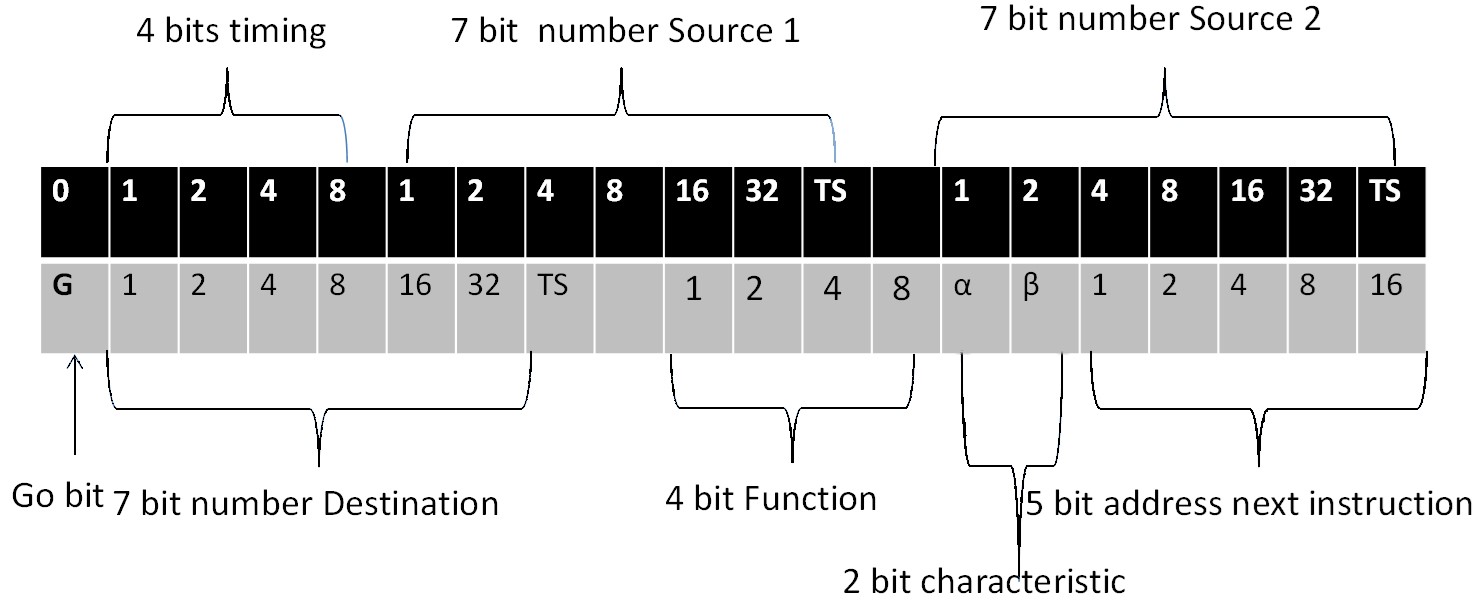
Figure 1
Figure 1 – Format of the MOSAIC instruction word

An instruction was represented within a 40 bit word, using the format shown in figure 1.

For example, the instruction to add the contents of short delay line 4 to those in short line 5, place the result in short line 6 and take the next instruction address as long line 27 is binary 0/1001/0010001/0/1010001/1/0110001/0/1011/10/11011. The function code of 1011 is the add function. (Note that MOSAIC numbered bits from the left to right, with the rightmost bit being the most significant.) The instruction is executed immediately (Go bit set), with the instruction execution being deferred, as indicated by the “α” bit being set, by the 9 minor cycles specified in the timing field. The 7 bit addresses are 0-63 (long lines), 64-95 (the 28 short lines and four double lines) and values greater than 95 as used for specific functions.

The two bit characteristic codes define the mode of execution as:

  • Immediate (characteristic=0) – The execution started on the first obey cycle and continued for a further n minor cycles, where n is the timing count. Once execution had finished the next instruction could be setup and then executed.
  • Deferred (characteristic=1) – The instruction executed for one minor cycle, scheduled for n+1 minor cycles after the setup beat.
  • Forced Discrimination (characteristic=2) – was a type of immediate instruction, with discriminate (a one minor cycle delay) automatically applied so that Setup for the next instruction occurred n+2 rather than n+1 minor cycles after the setup beat. No instruction was executed during this additional cycle.
  • Serial (characteristic=3) – For this the Obey Instruction Beat was 16 minor cycles with a gap of n minor cycles before the single execution minor cycle took place.
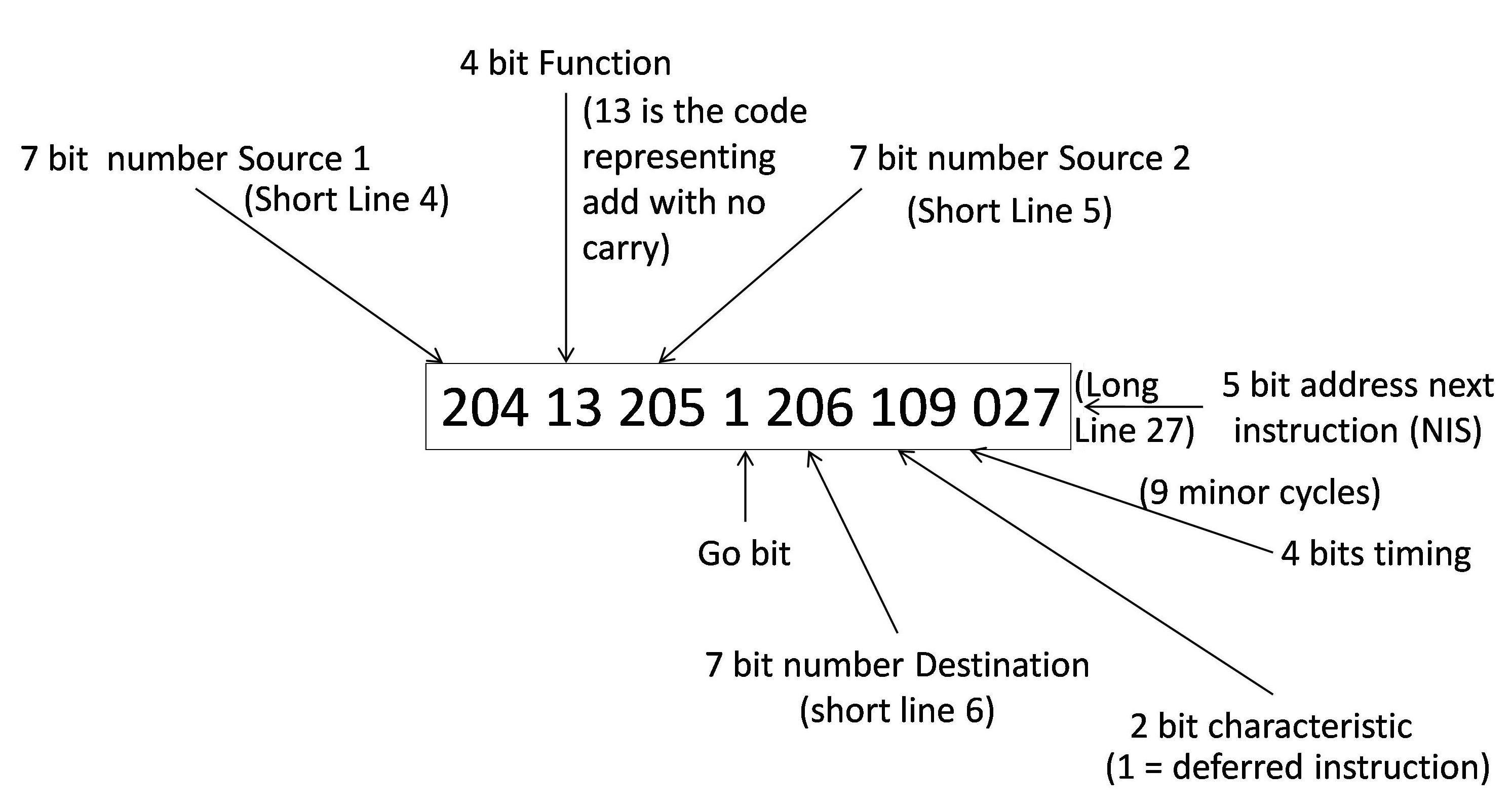
Figure 2
Figure 2 – format for encoding an instruction in decimal form

Input routines were developed that allowed instructions to be entered in a more symbolic fashion than a linear sequence of bits. Decimal coded instructions were punched one to a card and encoded using columns 11-28 and 10 rows of a single card. Using this convention, the instruction described above took the form given in figure 2. This method labelled long lines 0-31 as decimal 0-31 and 32-63 as 100-131; the short and double lines were signified as 200-231 and the special sources and destinations referred to using 300 and above.

The functions available were:

  • Null (No operation).
  • Signed and unsigned multiplication.
  • Logical functions of AND, XOR and OR.
  • Add functions that suppressed the carry on even, odd, all or no minor cycles.
  • Subtract functions that suppressed the carry on even, odd all, or no minor cycles.
  • A delay function which was effectively a right shift of up to 47 bit positions. Each shift position was a doubling of the number at the source 1 address.

The machine had a hardware multiplier which took up to 82 minor cycles to complete an operation. The results of the multiplication were held in a double delay line (the accumulator), labelled 231. (The other two double lines 228, 229 could be separately addressed and delay line 230 was a special address, which when loaded would automatically add its contents to the multiplier accumulator).

All operations were integer operations, any requirement for floating point being managed by the programmer defining the location of the decimal point in the data word and interpreting this consistently across the execution.

Programming Conventions

Programs were written using two mechanisms known respectively as the structure diagram, which incorporated flow charting techniques and the storage or sequence diagram. The structure diagram laid out the instructions in the order in which they were to be executed. This set out the logical flow of the program. The storage diagram allocated each instruction to a memory location determined by the timing, characteristics and Next Instruction Source of the previous instruction and the desired execution flow.

The final code once produced was encoded onto punched cards and was then verified by the programmer, who corrected any mistakes.

The efficient placing of instructions in storage, to make the best use of machine cycles, was known as Optimal Programming and gave the programmer greater control over the efficiency of execution; at the expense of complexity of programming.

Indexing

At the simplest level, MOSAIC could carry out simple vector manipulations without recourse to modification of instructions. For example just to add the contents of a five element array could be done using a single instruction:

      031 13 201 1 201 004 003

Timing the first obey cycle to reference the first element of the array in delay line 31, then for the next five cycles, the contents of delay line 31 are added to the contents of short delay line 1 giving their sum. This is shown in figure 3.
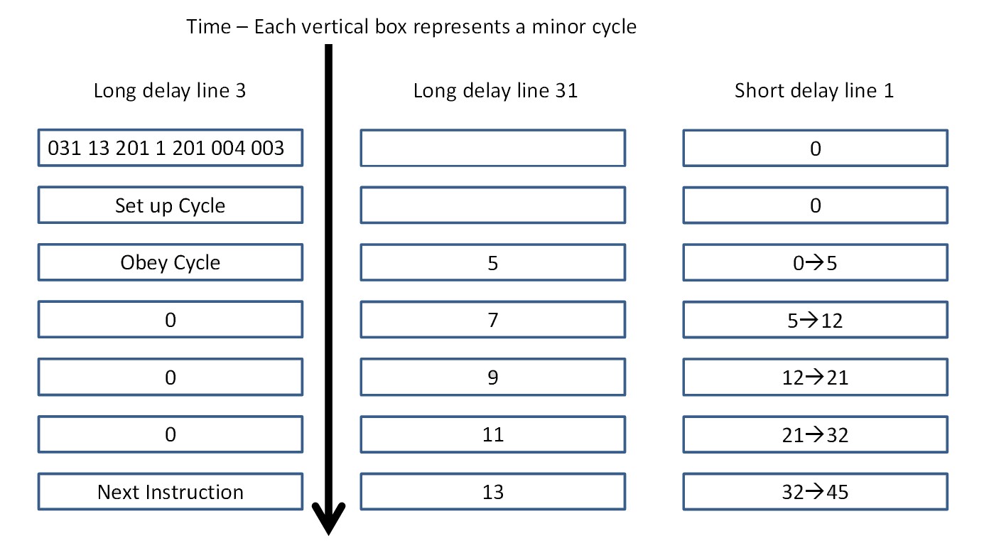
figure 3
Figure 3 – changes in memory during execution or instruction summing the contents of a vector (both the start value and the end value are shown for the short line.)
figure 4
Figure 4 – accumulating the modulii of a 16 element vector

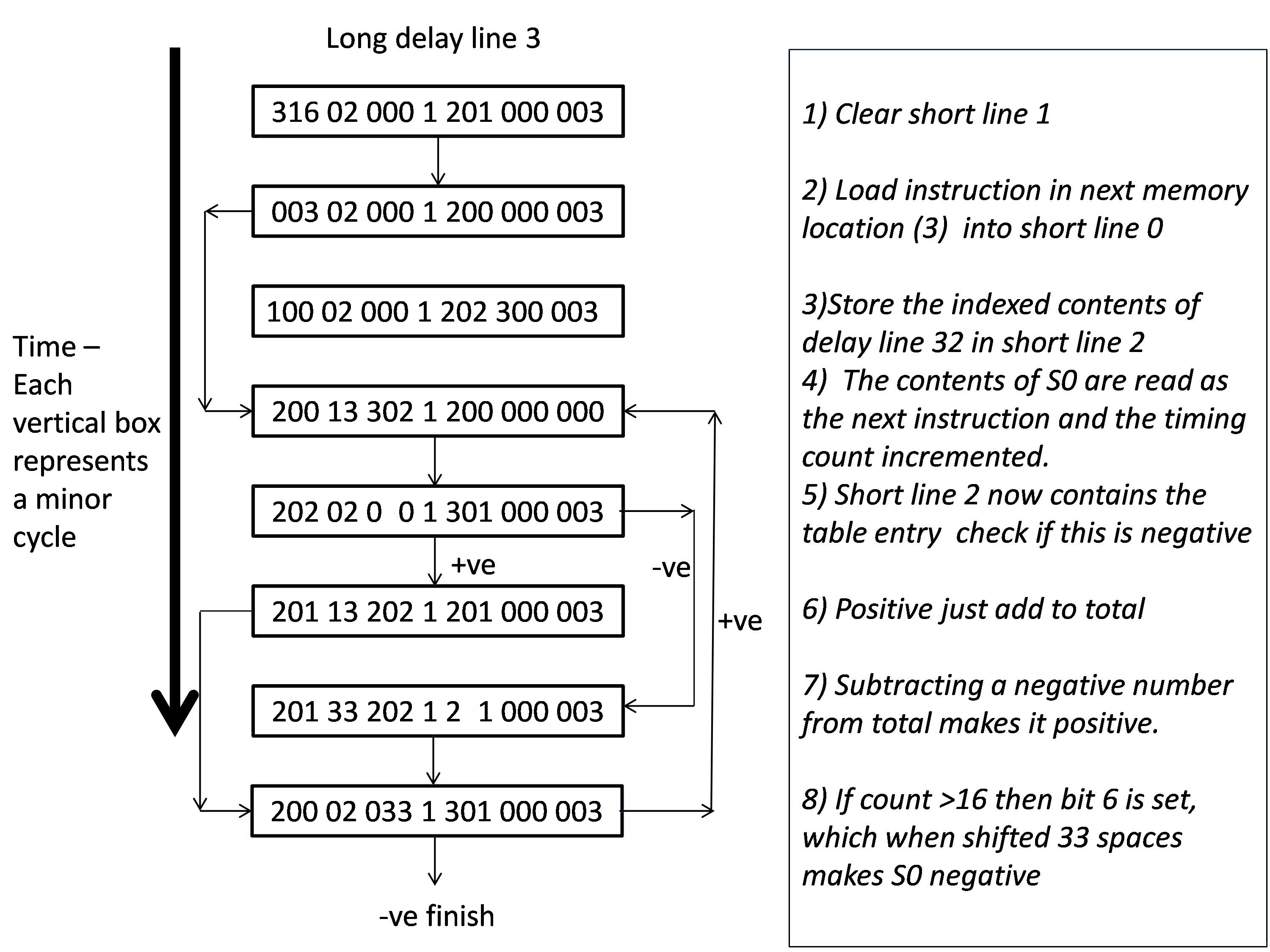
More sophisticated operations may require address manipulation as shown in the example below, where in an array held in delay line 32, the moduli of each element are added together in short line 2. This is shown in figure 4:

This example utilises conditional branches, special source and destination addresses, which will be described later. Short line 1 is first cleared, since this will be used to accumulate the sum of the array elements. The template of the instruction that will be used to extract the desired element from the vector is then loaded (but not executed) into short line 0. Instruction 4, then selects the instruction in short line 0 as the next instruction to be executed, before adding 1 to its count field. The instruction in short line 0 is a serial instruction and takes 16 obey cycles to execute, only transferring data from the vector specified in the source 1 field (long line 32) to short line 2 during the minor cycle specified in the count field.

Once this instruction has completed, the sign of the result is checked; if it is positive, it is added to the total in short line 1; if on the other hand it is negative then it is subtracted from the total, effectively adding it to the total in short line 1. The final stage is to check the effect of shifting the instruction in short line 0 33 places to the right. If the count has been incremented beyond 16, then it will have overflowed into the source 1 field making the shifted number negative. In this case the operation is complete, if not processing loops back to step 4.

This style of operation is clearly not for the faint hearted. It is possible to view the template instruction held at location 4 as an indexing mechanism; however the MOSAIC architecture did not explicitly accommodate an index register.

Special Sources and Destinations

In MOSAIC, special sources and destinations had specific meaning and were labelled using a value of 300 or more. Such sources or destinations were used in three cases; the first was the instruction to branch on negative or branch on a zero result. This has been alluded to in destination 301 in figure 4, as a test for a negative number. The second was for the loading of common bit patterns or numbers into store and the third was to allow and control input from the card reader and output to the card punch, both these functions being provided by a modified BTM tabulator device. An additional output device was a teletype writer device. Sources or destinations of zero had specific meanings (some are described later).

Jumps and Branches

Programs have two controls that when used together allow unconditional branching within a program, the timing count and the next instruction field. In programming, the completion of one instruction normally dictates where in storage the next instruction should be placed. However, it is possible to use these fields to execute an unconditional branch.
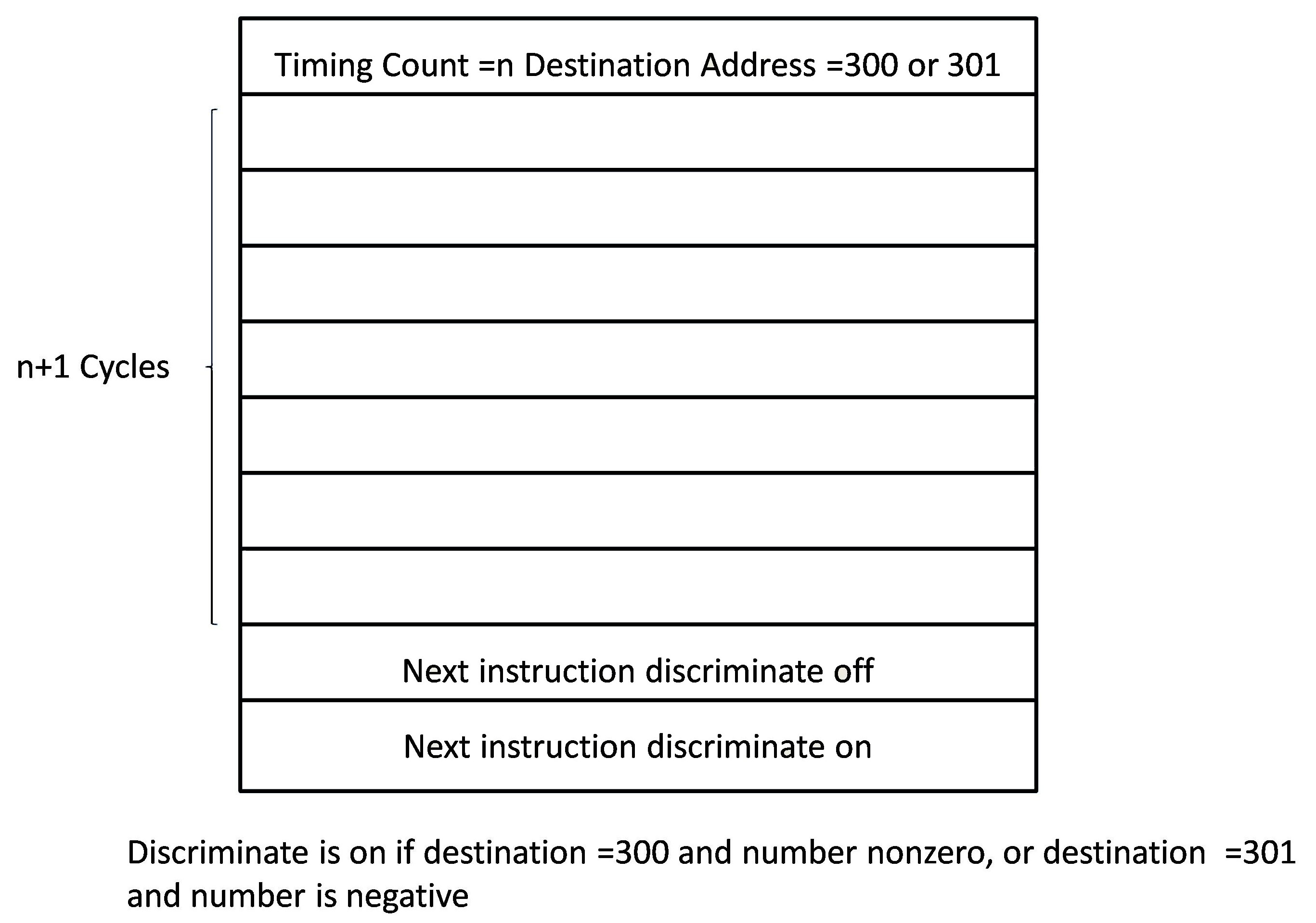
figure 5
Figure 5: Generalised conditional branching.

Two options for conditional branching exist based on special addresses 300 and 301, which respectively test if a storage location contains a non-zero number and if it is negative. In these cases a discriminate cycle is introduced. For example consider the instruction

      201 13 202 1 300 000 003

This will add the contents of short line 1 and short line 2 and if the result is zero, control will pass to the instruction two minor cycles on from this. If on the other hand the result is non-zero, then control is passed onto the instruction three minor cycles later (the additional beat is known as the discriminate cycle). This is generalised in figure 5.

Subroutines

MOSAIC also provided a mechanism to link to subroutines and hence allow the development of subroutine libraries.

A first order subroutine was defined as one that does not call another. It is called by a second order subroutine, which in turn may be called by a higher order subroutine, with the main routine being the highest order. Subroutines were always stored in consecutive long lines starting with minor cycle 0 of the first long line used. The first instruction to be obeyed in an nth order subroutine is the nth minor cycle of the major cycle. The number of the first line to be used is referred to as the address of the subroutine. Subroutines were called using a mechanism known as the Cue instruction, with return to the calling routine facilitated by a mechanism known as the Link instruction. Figure 6 shows the general layout of memory for a main routine executing in delay line 16, calling a third order subroutine held in delay line 5.
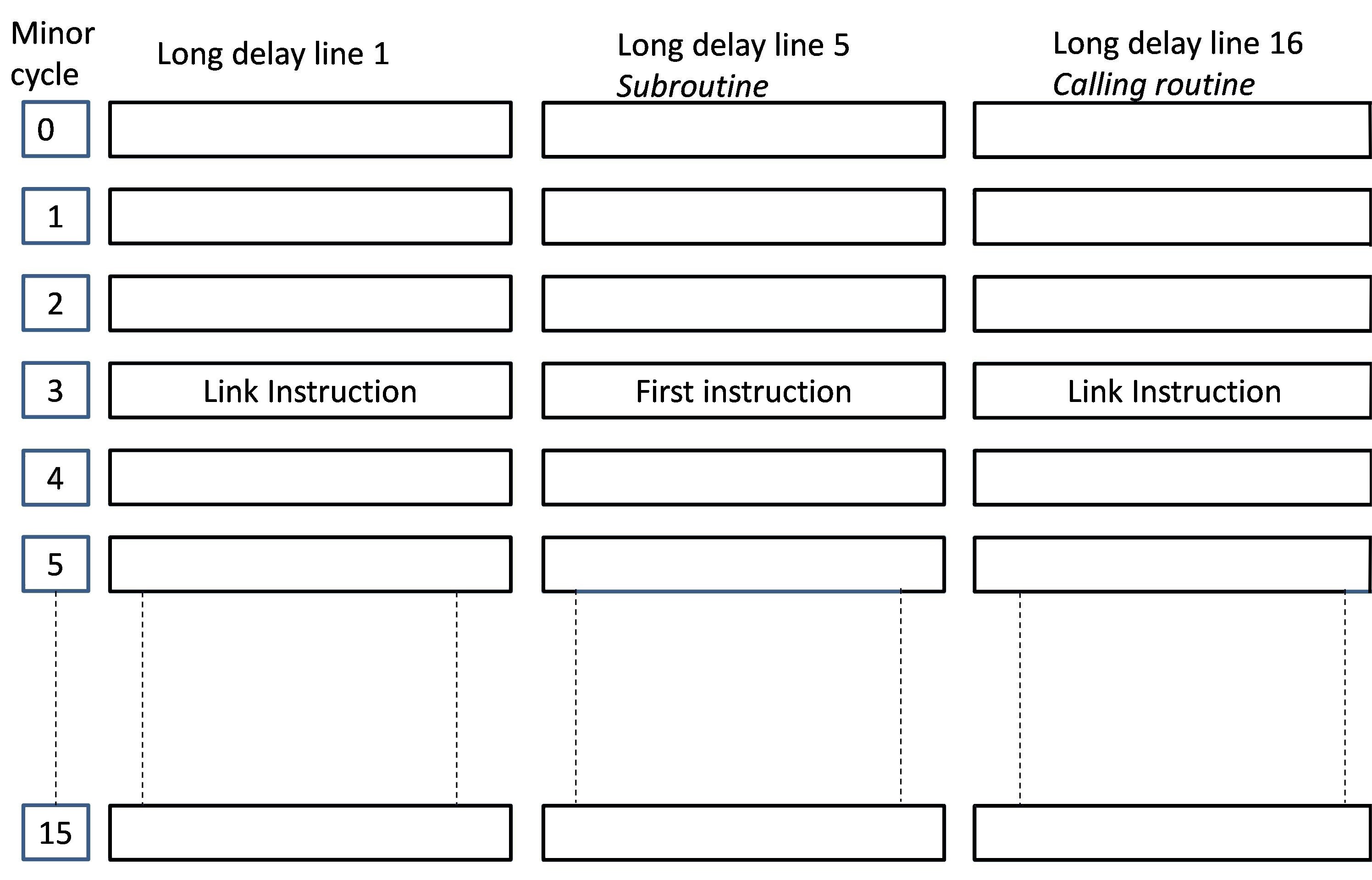
figure 6
Figure 6 – Memory allocation for subroutines

In this example the Cue instruction would load the link instruction into delay line 1 during minor cycle 3 and transfer control to delay line 5 during the same minor cycle. The instruction (in this case held at minor cycle 1 in delay line 16) to do this could take the form:

      016 02 000 1 001 000 005

If this is issued by the calling routine during minor cycle 1, it will take the instruction located in delay line 16, minor cycle 3, copy it to line 1 during minor cycle 3 and read the next instruction from delay line 5 at minor cycle 3, as the next instruction to be executed. The instruction placed in line 1 is the Link instruction. When the subroutine completes its processing, this is the instruction which needs to be executed to return control to the main program.

If this convention is followed then subroutine calls may be nested to a depth of 15, since the minor cycle (location in long line 1) reserved for the Link instruction for that subroutine is intrinsically associated with the order of the called subroutine.

Input-Output

Input to MOSAIC was through punched cards and output was either by card punch or by teletype writer using one of two character sets.

Binary input punched cards, with 80 columns and 12 rows, were used, with each row representing a single 40-bit binary number. Cards could be read at 200 cards per minute. Once the last row of a card had been read, the programmer needed to activate the card feed mechanism by issuing a “Hollerith Read” instruction using destination address 304. This took the form:

      201 00 201 1 304 000 003

assuming the program is running in long line 3. To read the next line of a card required an instruction that specified the first source address as “0000000” (known as the “Input Dynamiciser”) and the destination address as the address to hold the incoming card. This was a wait type instruction that would be obeyed when the card reader had completed its read of the current line. The transfer was followed by a new instruction being set up. Such an instruction would take the form:

      000 00 000 0 002 000 003

where the next line of the card would be read into long line 2. This mechanism is used to support the initial load of a program.

The Start button, on the machine front panel, was used to initiate a card feed. On initial load, the front panel Clear key needed to be pressed and released; this resulted in the current operation being suspended and the zeroth instruction consisting of all zeros was queued. By definition this is a Wait instruction, which would have no impact until the first row of the first card was read, following the operator pressing the Start button. Since this instruction had a destination address of zero, the incoming card would be used to form the next instruction. One possible sequence of card lines would be:

      200 33 200 1 200 100 000
      200 00 200 1 302 100 000
      200 00 200 1 304 000 000

Here the zeroth instruction would read in and execute the instruction on the first card, which would have the effect of placing all zeros in short register 0, which would form the next instruction. This would be a zeroth instruction, which would read in and execute the second card, which is a reset of the output device (Staticiser Reset instruction) and specifies the short register 0 as the next instruction. Again this forms a wait instruction, which completes when the third card is read in. The third card then issues a Hollerith Read command to initiate a card read and queues a zeroth instruction as the next instruction. In this way a chain of input instructions is set up.

The first line of the next card to be read would begin the process of loading the instructions which would allocate the user program to specific locations in memory. This typically would be instructions to read the load sequence into a temporary storage area, interleaved with the actual load sequence instructions. These would take the form:

      000 00 000 0 002 113 000    (Card type 1)
      000 00 000 0 003 115 002    (Card type 2)

the first card reading in the second and placing it in long line 2 and the second is the instruction to read in the next line of the user program. The next instruction executed after the first card is obeyed is the zeroth instruction, which will normally read in the next card of type 1. The timing count of 13 specified ensures that the instruction on the next card of type 1 read in will be executed 17 (i.e. 1) minor cycles after the previous type 1 instruction.

Once all the type 2 cards have been read in, then the load of the program can be initiated by loading a card that transfers the execution path to the delay line holding the type 2 instructions. An example of this, where the code to be executed in long line 3, would be:

      200 00 200 1 304 100 003

Note that the timing count would need to be adjusted so that the main routine would be entered at the right point of execution.

Where more than 12 rows are needed, the instructions described above would need to include a Hollerith Read instruction, and this would affect the timing, requiring adjustment of the timing count for some instructions. The input process was generalised as a standard input routine, which occupied four long delay lines. The “decimal number input subroutines” were two subroutines that were auxiliary to the instruction input subroutine and allowed it to read in numbers punched in decimal form. These routines provided the input mechanism used for the decimal coded instruction format already described.

Output was to a special destination (303), known as the Output Staticiser, which could be diverted to a specific device using the following special destinations:

  • 305 caused any subsequent output directed at special destination 303 to be directed to the card punch.
  • 306 would direct output to the teletypewriter
  • 307 would direct output to the teletypewriter using an alternative character set.

If punched cards were selected for output, the punch was set in motion by issuing a “Hollerith Punch” instruction (special address . 303), which caused one card to be passed under the punching mechanism. For example in the instruction sequence

      201 00 201 1 305 100 003
      201 00 201 0 303 100 003

first selects the Hollerith Punch and then sends the contents of short line 1 to the punch. Note the latter is a wait instruction, the wait condition being satisfied once the punch is ready.

Data was initially produced in binary form, until the necessary mechanisms to convert between decimal and binary were created. A reproducer was used as the output device and a modified tabulator for input. For input and output, the card reader could be used as a slow-speed back-up store.

Printing to the teletypewriter was initiated by sending a word consisting of a single bit, representing the desired character, and all other bits zero to the device, using special destination 303.

The Output Staticiser needed to be reset to all zeros between uses. The “Staticiser Reset” was applied automatically after a punching, but for the first read-out of a calculation, the starting program for all calculations required a Staticiser Reset instruction (Destination 302).

Test facilities

MOSAIC had a front panel which provided a number of control and debugging capabilities. This had four functional capabilities, the first of which was the ability to set the contents of an instruction word using 40 switches, each switch representing an instruction bit. These could be used to load a card into the Input Dynamiciser.

There was an array of 40 lamps which showed the bit values of the current instruction being executed or the contents of a specific memory location.

The console itself had three lamps that reflected the current state of the machine, one showing the machine was under test and not available (red), one showing that the power was on (yellow) and one showing if the machine was in a wait state (green). One switch allowed the output to the card punch to instead be diverted to the array of 40 lamps. Another switch allowed the current instruction to be displayed on the array of lights. There was also a three way switch that could inhibit the go bit instructions, allow the machine to operate normally or inhibit the normal execution of instructions.

Finally there was a step button, which allowed instructions to be obeyed step by step. There was also the button to start the card reader.

There was a set of 10 switches that effectively provided a break point function. Five of these could select the long line carrying the instruction to be executed. Four would select the desired minor cycle on which to stop the sequence of instruction executing in the selected long line. The 10th switch enabled the interception of the selected instruction and prevented it from running.

When a program was being tested an examination subroutine could be installed. This enabled the contents of any storage location to be viewed, control to be passed to any storage location and store to be filled with a word set on the id keys. Control of the examination routine was achieved using the front panel controls.

Outside of these capabilities there were no further exception handling controls.

A Coding Example

As an example, I include the program described in my previous paper ( Resurrection101 ), which identified the highest factor of a number N, by beginning with a solution of a=N-1 and decrementing it until a value is found that is a factor of N. Each number a is repeatedly subtracted from N until a remainder of zero is seen, if the remainder is positive then a is again subtracted, if it is negative then the solution a =a-1 is tried. The logic followed is shown in figure 7 below.
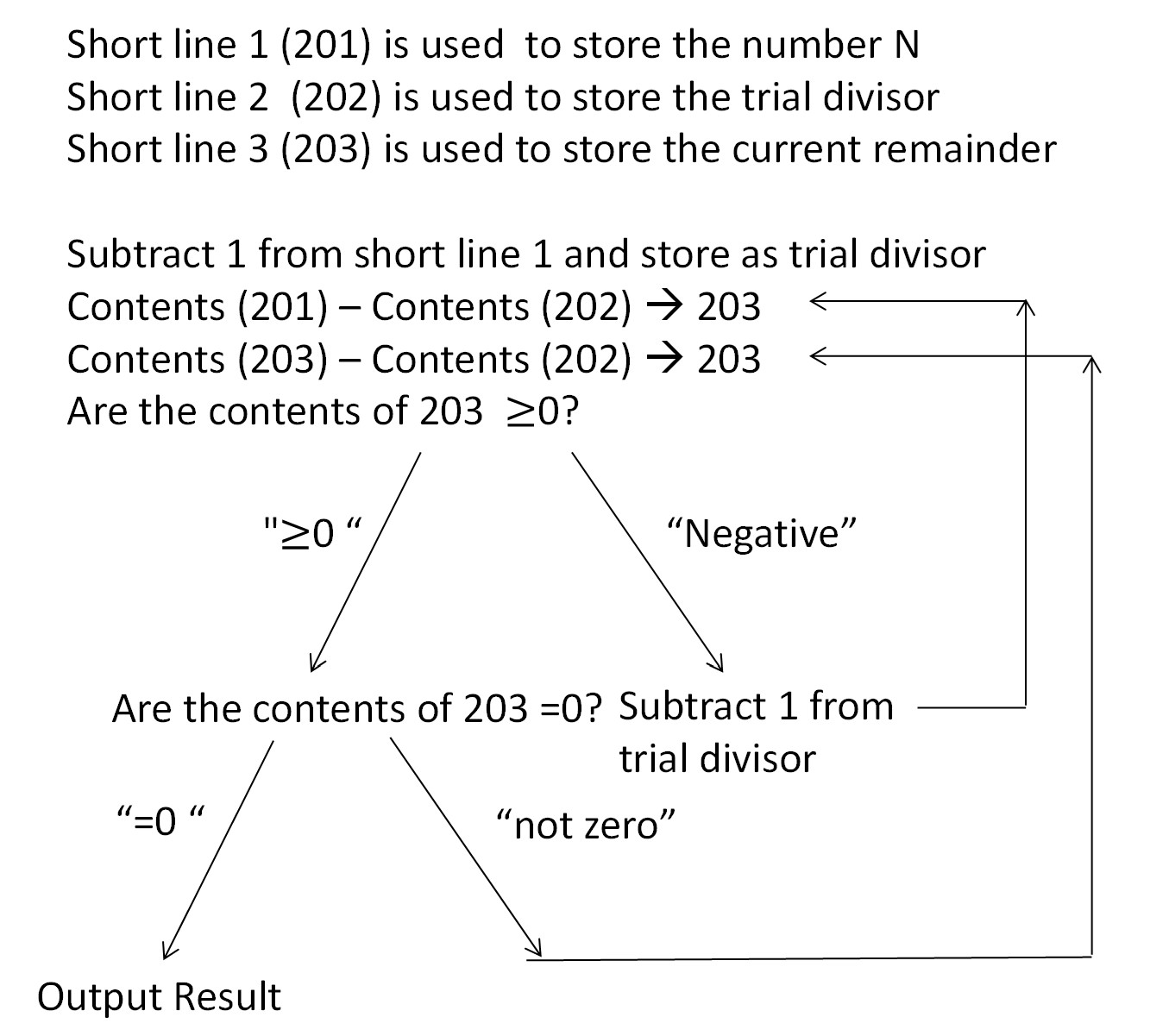
figure 7 figure 8
Figure 7: Logic flow of highest factor program Figure 8 – Memory allocation for code for highest factor program

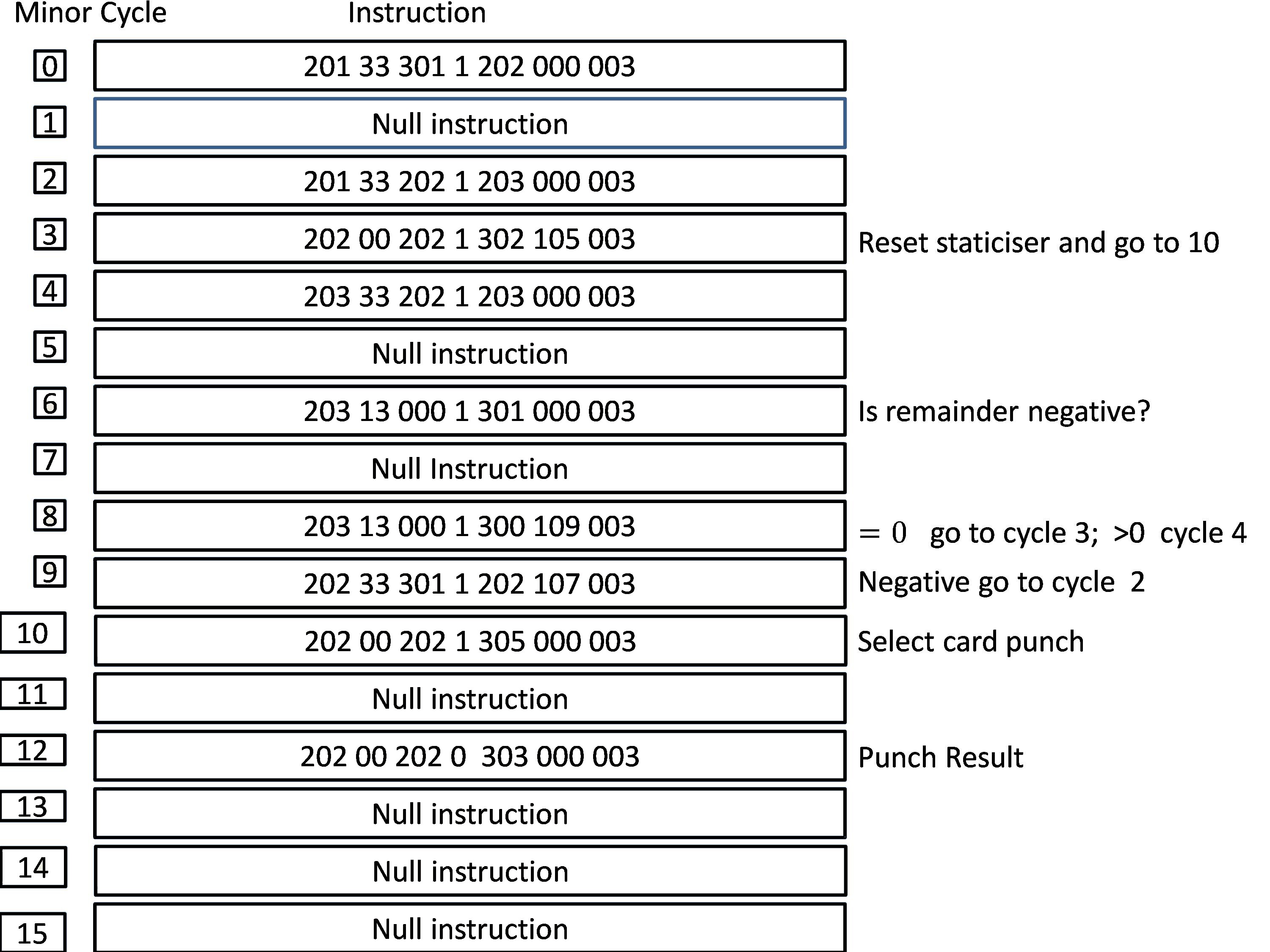
This first needs to be translated into a series of instructions and these instructions then need to be allocated to a given memory location, as shown in figure 8.

The logic of the program is as follows: subtract 1 from N and store the result in short delay line 2 as a. The next step is to store the difference between N and a in short line 3. Subtracting short line 3 from short line 2 gives the value N-2a which is stored in short line 3, this will probably be negative for the first number a, but for smaller a may be positive (NB each step takes a minimum of two minor cycles).

The sign of the value in short line 3 is tested on minor cycle 6, if it is negative control is passed to the instruction at minor cycle 9, where a new trial divisor is formed and stored in short line 2 and the program is re-entered on minor cycle 2.

If, on the other hand, the value in short line 3 is positive, it is tested at minor cycle 8 to see if it is zero. If this is the case control is passed to the instruction at minor cycle 3, which resets the output staticiser. The correct answer is now in short delay line 2, but the instruction to select has been placed at minor cycle 10 as the most convenient next location. This is reached by specifying a timing count of 5 on the reset output statisicer instruction. If on the other hand short line 3 was not zero, control is passed to the instruction at minor cycle 4 and the main loop is iterated again.

Conclusions

Only one MOSAIC machine was ever built and neither it nor any reconstruction exists today; nor is any emulator readily available. This paper has been developed based on available documentation and an experimental emulator, currently under development.

MOSAIC was a powerful and versatile computer, however unlike EDSAC, its underlying dependence on delay lines was not hidden from the user. This made programming more complicated and potentially error prone. Through a technique known as optimal programming the number of wasted memory cycles could be minimised.
Top Previous Next

A Disappointingly Quiet Birthday

Dik Leatherdale

In June 1998, there was a great gathering at the University of Manchester to commemorate the 50th anniversary of the Manchester Baby computer, arguably the first electronic stored program computer. The autumn of 2024 marks another 50th anniversary, that of the ICL 2900 Series – an anniversary which has passed almost unnoticed. Sometimes called ICL’s “New Range” it was the last in a long line of UK mainframe computers descended from the Baby. Over the last 50 years, the name has changed several times, but its essential nature has not. Though New Range is not the star it was in its heyday it is still out there happily crunching data and earning its keep. So this is the story of some of the earliest models. In many ways the 2900 Series software is just as interesting as the hardware, but perhaps that is for another day.

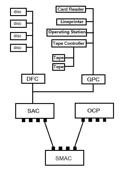
The (logical) boxes and their interconnections.

We will commence by considering the very earliest 2900s known as the “P Series”.

A basic P-Series configuration
A very basic P-Series configuration. Two or four SMACs would have been usual and was de regueur on 2970s and 2980s.

One of the original design objectives was to relieve the main processor of the tiresome duty of servicing peripheral transfers. This was not a new idea. The Control Data 6600 employed a bank of small, inexpensive processors to do all the donkey work leaving the CPU to think beautiful thoughts. In the ICL world, 1900 CPUs were commonly relieved of the tedious task of interacting with disc drives with an intermediate processor, the PF56.

It is always helpful, when describing any computer to start with the store. All 2900s had semiconductor store. By 1974, the era of core store was largely behind us. Many readers will recall the rapid development of semiconductor stores in the 1970s. The 2900 Store Multiple Access Controller (SMAC) was host to 1Kbit, then 4Kbit and finally 16Kbit modules as the technology advanced. The price per bit dropped rapidly leading to an increase in the amount of store being affordable and whereas 1½ megabyte machines were regarded as a sensible minimum in 1974, 3 and 4 megabyte stores became common in the last years of P-Series. As we shall see, this had an effect on the wider design of the machines.

ICL’s SMAC was not a new idea. Certain 1900 models had SMACs so the notion was well proven. Each SMAC had four connections to the outside world known as “ports”. But a basic configuration was viable using just two ports. One port was connected to an “Order Code Processor” – always known as the “OCP”. In other contexts we might refer to this as a “CPU”. The OCP was the powerhouse of the machine but again, a detailed description is outwith our narrative today. Suffice to know that it had the capability of being connected to up to four SMACs and that, although a typical 2900 had a single OCP, two were sometimes fitted for resilience and capacity reasons.

More interesting is the “Store Access Controller” (SAC). The SAC was the gateway to the peripherals and thence to the outside world. Again, SACs had the capability of being connected to up to four SMACs. One SAC would be a theoretical minimum, but two was common. It is tempting to say that three was possible, but I never came across a configuration with three SACs. The purpose of the SACs was to act as a coordinating intermediary between the store and the peripheral controllers. Both OCPs and SACs were fitted with four possible connections allowing up to four SMACs to be employed with every SAC and OCP being connected to every SMAC and vice-versa.

Which brings us to the next layer – the peripheral controllers of which there could be up to eight per SAC. Peripheral controllers were each driven by a dedicated control program always referred to as “microcode”. Let’s look at them one by one.

  • Sectored File Controller (SFC). Acted as an interface to one to three (but usually one) fixed head discs (FHDs). FHDs were much faster than ordinary discs and hence were only used for main store paging. Which is why, for historic reasons the fixed head discs were often erroneously referred to as drums. Three models of FHD were available in 2MB, 6MB and 5MB sizes with the later 5MB size (bought in from Burroughs) being the most common. As the price of semiconductor store reduced and consequently main store sizes increased, FHDs became less useful and were eventually dropped from the catalogue leaving a stock of unused FHD5s in storage (apparently in the Nevada desert) a few of them being used for spares as the operational FHD5s wore out (but again, that is another story). Once the FHDs were full, paging to exchangeable discs was somewhat slower.
  • Disc File Controller (DFC). Again, an interface to up to 16 exchangeable disc drives. Initially 100MB drives (EDS100s) were available, but these were soon superseded by EDS200s. In both cases Control Data was the manufacturer. EDS60s could be brought forward from 1900s and System 4s but this was rare.
  • Because the operating system was loaded from disc, the DFC microprogram had to be present before system loading could begin. Hence the presence within the DFC of a ⅛” cassette tape drive as developed by Philips as long ago as 1963.
  • General Peripheral Controller (GPC). An interface to up to eight peripherals of different types –
    • Operating stations
    • Lineprinters
    • Card readers
    • Card punches
    • Paper tape readers
    • Paper tape punches
    • Online graph plotters (probably never sold any)
    • Magnetic tape controllers (see below)
    • High performance configurable communications controllers (7905/6/4 actually CTL Modular 1s).
  • Communications Link Controller (CLC) or Communications Network Processor (CNP). Based on the same engine as the ICL 2903, these devices provided links to interactive terminals – usually ICL 7502/7561 clusters. The CLC was a simple device with no capacity for user configuration, whereas the CNP allowed the user some flexibility and greater capacity than the CLC albeit less than the 790x.
  • The last type of controller was an odd one which arose from a requirement by the Department of Social Security to process data faster than could be delivered by the existing types of disc drive or magnetic tape. The requirement was satisfied by Control Data’s top of the range 1.25MBytes/sec magnetic tape drive which ICL christened the MT1250. Utilising Group Coded Recording (GCR) the MT1250 was too fast to be connected through the GPC like other magnetic tapes so a special controller had to be designed and implemented. Aside from the DSS, there were no other takers.

Connections for resilience

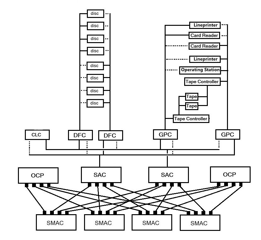
It is tempting to see the SAC/controller/peripheral structure as a pure hierarchic tree. That might be possible but it wasn’t usual. In order to guard against device failure, it was possible to connect any of the controllers to two different SACs (where available, which it usually was). Thus, the computer could be reconfigured by means of switches mounted on the operating station console or on the controllers. Similarly, peripherals could be switched between controllers of the same type. In this way a high degree of resilience against controller failure could be achieved.

A common configuration was to have two DFCs each connected to all of the discs and two GPCs each connected to most of the “general” peripherals. Two SACs each cross connected to two of each type of controller was also common for the same reason.

Magnetic tapes

The standard magnetic tape types were the MT120, MT200 and MT320 (the names give us the speed in Kbytes/sec). Uniquely the magnetic tape drives were not connected to the host GPC but to yet another layer in the hierarchy, the Magnetic Tape Controllers. It was common for banks of four transports to be driven by two controllers. Each controller could only drive one transfer at a time but with two controllers two transfers could be in progress at the same time. Switching tape decks between controllers was entirely automatic no operator intervention being required.

More resilience and performance

Although we have considered machines with a single OCP, one SMAC and a single SAC, it was usual to have two or four SMACs and two SACs with extensive switchable cross connections as discussed above. Adding a second OCP added additional power and resilience against processor failure and allowed the dual processor configuration to be divided up into two single processor systems should the need arise.

Attached Emulation

In order to support transition from ICL’s existing mainframe ranges, it was proposed to allow 1900 and System 4 CPUs to be attached to 2900 configurations. How this was to be achieved is something of a mystery to the present writer but that is not a matter of any import because the proposal, though developed and announced at launch failed to attract any sales and so never escaped into the wild.

A rather more resilient P-Series machine

P-Series models

Consulting Martin Campbell-Kelly’s excellent book ICL a Business and Technical History , we learn that the initial plan was to design no less than six different models internally designated P0 to P5. P5 was abandoned quite early because it was estimated that the likely volume of sales in a market dominated by Control Data and IBM would not cover the substantial development costs. P0 also hit the dust, though in this case the reason was that it could not be manufactured at a cost which would allow the selling price to be attractive.

At this juncture (the early 1970s) ICL had recently launched the 2903 (a 1900 order code machine) which was selling spectacularly well at the bottom end of the mainframe market. It was decided to launch the 2900 range with the P3 and P4 so as not to cut into the 2903’s market. So the P1 and P2 were never seen, at least not as originally envisaged.

The 2970 and 2980

1973 should have been the launch date, but it was not to be. New Range (the term 2900 had not yet been announced) was late. So late, in fact, that the much-missed trade paper Computer Digest would often sarcastically refer to it as the “Not Yeti”. So it was that in October 1974, the P3 and P4 were announced as the 2970 and 2980 albeit that the 2980 was not quite ready to be delivered.

The top of the range 2980 was a “proper”, hard-wired computer roughly equivalent to the contemporary IBM 370/168. Most 2980s seem to have been delivered to government installations, being the users most likely to be able to utilise such a monster.

The 2970 was a microprogrammed machine albeit one with some hardware assistance to the microcode. Prior to the launch there were several 2970s in existence used for software development inside the company. Thus, by then it was a reasonably stable platform. Most 2970s were delivered to private sector customers and to second-tier government organisations.

We have mentioned the unused “attached emulators”. The 2970, being a microprogrammed machine was, with the addition of some extra circuitry, able to run an emulated 1900 or System 4 hosted within the VME/B operating system. The present writer had the dubious pleasure of installing and configuring the software on two 2970s each with a different type of hosted emulation.

It was discovered that the object code produced by the COBOL compiler was rather less efficient than it might have been. So, after some serious deliberation, it was decided to fit an additional register and the circuitry to support the instructions which utilised it. The upgrade was fitted in the field to every extant 2970 and 2980 an operation which, though complex, was carried out with surprisingly little trouble and at no cost to the owners.

The 2960

1976 saw the introduction of a further model in the range, the 2960. It is tempting to see this as our old friend the P2. But it wasn’t – well not quite. Its internal designation was the P2L. Did “L” stand for “late” Unlikely but possible. A 2960 configuration was pretty much the same as that of the 2970 except that a new microprogrammed OCP known as “Micos2” replaced the 2970 OCP. Being based on somewhat later technology and lacking the hardware assistance features of the 2970, the 2960 OCP was considerably cheaper to produce than the 2970. A further economy was made by replacing the complex bank of switches and indicator lamps at the end of each P3/4 OCP cabinet by a keyboard and CRT on the 2960. It was also more reliable than either of its elder siblings. The 2960 OCP was designed in the Stevenage office rather than in Manchester where the 2970 and 2980 originated.

The 2960 offered a choice of microcodes – for 2900 order code, for 1900 and for System 4. At the request of the Post Office, an additional microcode was produced for emulating Leo326 to replace their now aging and difficult to maintain Leos. At first the 2960 was only able to run one of the microcodes at a time, but later the system was enhanced so that two different order codes could be run side by side unlike the 2970 facility for hosting one inside the other.

In some ways the 2960 was the most successful of the P-Series models, but the profit margins were desperately thin what with all the SACs, SMACs and controllers which were no cheaper to produce than they were for the bigger machines.

The 2976 Saga

One thing we have omitted to mention is that the 2970 and 2960 SACs, SMACs and OCP differed from those on the 2980 in that the data highways from the SMACs delivered 64 bits at a time in parallel, whereas those of the 2980 delivered data in 128 bit chunks. 2980s sold in comparatively small numbers so if a means could be found of marrying a 2980 OCP to 2970 SMACs and SACs, the production cost could be lowered. The means of achieving this was for the P4 (2980) OCP to request two 64 bit chunks of data, one after the other from the P3 SMACs. This was launched as the 2976. Sadly, performance was less than sparkling and, more importantly, less than promised. Back to the drawing board then. The second solution was to pair up the SMACs so that the OCP would simultaneously receive 64 bits from one SMAC and 64 bits from its sibling. All new 2976s followed this strategy. Extant 2976s in the field were upgraded at ICL’s expense and the original 2976 design was relaunched as the 2972, finally allowing the 2970 and 2980 to be withdrawn from sale.

The Cache machines

These days we take cache memories for granted. The PC upon which this article is being written has an enormous cache memory in which copies of data which has been accessed recently are stored within the CPU in case (as is quite likely) the same data is required again in short order. Back then it was fairly novel. ICL decided to apply caching to its top of the range models. Applied to the 2976 and 2972, two new models were announced as the 2982 and 2977. But by this time P-Series 2900s were coming to the end of their sales life and few were sold.

Enter the S-Series

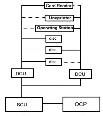
Readers will recall that I alleged that the 2960 wasn’t terribly profitable because of the complex network of SMACs, SACs and controllers the cost of which loomed ever larger as a proportion of the whole as we moved down the performance scale. So the most visible difference was a simplification of the hardware. The various P-Series controllers were swept away and replaced by a single type, the Device Control Unit (DCU). The functions of the SAC and SMAC were merged into a new device type, the Store Control Unit (SCU). These changes allowed economies of scale in the manufacturing process to be realised. I say a single type of DCU, but there were two variants. One had the facility to allow the system bootstrap to be initiated from one of its subordinate disc drives. The other allowed ICL’s data search hardware the Content Addressable FileStore (CAFS) to be attached to it. A later variant absorbed the CAFS unit. The introduction of the DCU and the SCU had a favourable impact on manufacturing costs.

The onward march of semiconductor technology had also shrunk the physical size of much of the hardware including the OCP. So much so that the various boxes associated with P-Series were no longer required so the store, the OCP, SCU, store and the DCUs could all be accommodated in rather fewer cabinets, further reducing manufacturing costs and helping to restore competitiveness.

A modest S-Series configuration

In contrast to the launch of P-Series, to relieve pressure on margins for the 2960 S-Series was announced at the bottom end of the range with the top end to follow.

The initial announcement for S-Series was S2, the 2956 – a machine roughly equivalent to the 2960 the OCPs of the two machines having much in common including the ability to be microcoded as 1900s. I was told that unless we sold 400 2956s, the company would be driven into bankruptcy. We got nowhere near that figure and yet somehow, ICL survived to fight on. The 2976 and its variants continued in the catalogue and sold steadily for a while.

Not far behind was the 2950 (S1), a markedly more successful machine albeit with a diminished performance level. A slowed down version was launched later as the 2946 and a speeded-up version was given the name of 2955. Readers may also recall the skunkworks 2905 which featured in Resurrection 80.

The 2966

In 1981, the last 2900 to be introduced was the 2966. Known inside ICL as the S3 – sometimes S3E. (“E” = “early”? Maybe, maybe not.) After years of struggle the 2966 was outstandingly successful attracting orders from the traditional ICL customer base, from users of non-ICL systems and from organisations with completely new requirements.

The march of time and the consequent development of semiconductor technology allowed the 2966 to sit atop of the 2900 range, but although it had an improved OCP, all the other elements (or at least re-engineered versions of them) were shared with its smaller siblings albeit occupying more cabinets. Slugged versions later appeared as the 2953 and 2958.

Dual Processors and More

Dual processor versions of some of the S-Series computers were also possible, but they did not follow the P-Series philosophy of two OCPs connected to a common store. Each OCP had its own store. At any given time, a process would run in one or other of the OCP/store combinations (known as “nodes”, each node contained within its own cabinet) and although a process could move between nodes, this was accomplished by rolling out the local store of the process onto backing store and rolling it back into the other node. Some parts of the store image were common to all processes (i.e. the “public store”) and this was replicated in both nodes. By the use of a very fast interconnection between the two stores, an update to any part of public store in one node would immediately be applied to the corresponding location within the other.

Now I know I said that S-Series dualling differed from that in P-Series, but that is not entirely true. For it was possible for two OCPs to run in conjunction with a single store. This design was launched as the 2988. And, just for good measure 2988s could be joined together as a “superdual”, giving a system with no less than four OCPs in total, a top-of-the-range combination indeed!

Adieu

It is at this point that the 2900 saga ends. In 1985, the next generation arrived with a change of name – “Series 39”. Quite why is a mystery. Perhaps Marketing had just run out of numbers. But I can’t resist the temptation to dip my toe into that particular body of water. For the more powerful of the two processors in that range was often known as “Estriel” – a name bestowed by Fujitsu staff who had difficulty in pronouncing “S3L”, “L” once again supposedly standing for “late” (or not) as you will have guessed.

With Hindsight

The ICL 2900 came late to the market. It was designed to do what some of its main rivals had been adapted to do but were not designed to do from the off. Lessons had been learned and they had been learned well. But lateness brings its own problems. The need for big mainframe class computers had, to a large extent, already been satisfied by earlier machines and once systems had been implemented it was expensive and often disruptive to start again without a very substantial differentiating advantage which 2900 could not provide.

But 50 years on, some of 2900’s progeny are still out there doing useful work. That can surely be regarded as a success. So, New Range, happy birthday then!

Hat tip for their help to John Harper, Delwyn Holroyd, Vince Celano, Peter Byford, Vince Bosworth and Bill Gallagher. They are blameless. Errors are all mine.

Top Previous Next

Obituary : Brian Spoor

Bill Gallagher and Delwyn Holroyd

Brian Spoor sadly passed away on 16th May 2024, after a battle with cancer. He was a key part of the CCS 1900 preservation efforts and readers of Resurrection will have seen his reports over the years.

Bill Gallagher writes:

I met Brian through our collaboration on the preservation of the ICL 1900 series, its software and hardware. That started some 20 years ago when I contacted him after discovering his excellent website (www.icl1900.co.uk). His knowledge of all things 1900 was not only broad but deep. Without his enthusiasm, we would not have the great collection of material of all sorts which has been made available by Brian on his website.

Over the time that I knew him, he was always a source of not just technical information, but also examples of real-world usage and a great teacher as far as I was concerned. His ability as a project leader was frequently useful to prevent too many side-tracks from the main 1900 emulation efforts, although some of those side projects proved rather fruitful – the PF56 project was initially seen as a closed box but somehow, he found manuals, software and even people who worked on it. That constant energy to extend and improve our emulations and his website to make the ICL 1900 series and its related systems accessible and usable continued right to the end.

Not only a source of knowledge on both hardware and software which he was always able to take time to share, he had a deep and broad experience of how 1900s were used by customers. He had to remind me that compared to even half-modern standards, the 1900 was essentially simple. His guidance was much appreciated when I got too close to a problem and could not see the bigger picture.

Lastly, but far from least, he was a valued friend. The CCS effort regarding the preservation of the ICT/ICL 1900 series is much diminished by his passing.

Delwyn Holroyd writes:

I met Brian when he became one of the first users of the George 3 Executive Emulator, written by David Holdsworth and myself. Brian proved to be an excellent tester and managed to find all manner of strange bugs, quite often these were due to gaps in our knowledge of exactly how the hardware should behave.

At that time Brian was just starting to put together his website, now the foremost online collection of information on the ICL 1900 series. His tireless efforts in tracking down and collecting documentation has helped to fill in a lot of those knowledge gaps, and has enabled the creation of the detailed hardware emulators he has worked on with Bill.

Brian was extremely knowledgeable and I would frequently ask for his help to answer 1900 questions and solve various problems. That we were able to create a custom patched George executive for the ICL 2966 at TNMoC is a testament to his efforts in understanding how executives work and how they could be built in the absence of the original tools.

Despite living in deepest Devon, Brian was in recent years a regular face at CCS meetings and of course, at the pub afterwards. He would make this mammoth 10 hour round trip by train, truly dedication to the cause. These were the only occasions I met Brian in person, our collaboration being mostly via email.

After his wife passed he would often take himself off to Italy for extended periods to escape the miserable UK weather, but would still find time to work on his 1900 projects. We shall all miss him.

Contact Details

Readers wishing to contact the editor may do so by email to , or by post to 124 Stanley Road, Teddington, TW11 8TX.

Members who move house or change email address should go to www.computerconservationsociety.org/membership/membership_general.htm .

Queries about all other CCS matters should be addressed to the Secretary, Rachel Burnett at , or by post to 80 Broom Park, Teddington, TW11 9RR.

CCS Website Information

The Society has its own website, which is located at www.computerconservationsociety.org . It contains news items, details of forthcoming and past events and also electronic copies of all past issues of Resurrection, in both HTML and PDF formats, which can be downloaded for printing.

At www.computerconservationsociety.org/emu/index.htm can be found emulators for historic machines together with associated software and related documents all of which may be downloaded.

Top Previous Next

Fifty Years Ago .. from the pages of Computer Weekly

Brian Aldous – TNMoC Archivist

More users line up for ICL’s New Range: The long awaited ICL New Range, two models of which are now expected to be officially announced next month, is building up an impressive batch of customers, including university, commercial and government installations. The models, which are earmarked for unveiling in October, are the 2970 and 2980, better known as the P3 and P4. As the long-awaited announcement by ICL of its 2900 series, or New Range, due for the middle of October, becomes even more imminent, details of the first university and commercial orders are now beginning to leak out. In October, ICL will reveal full details of the two larger systems in the range, the 2970 and 2980. (CW 409 5/9/1974 p1)

Cash terminals plan by Lloyds: Once again Lloyds Bank has taken the lead in introducing new automated customer facilities to the UK. It is planning to install Cashpoint cash-dispensing terminals into stores and offices, and to have on-line automatic teller terminals outside bank branches. Both devices are manufactured by IBM. Lloyds has now completed its first phase of IBM 2984 Cashpoint terminal installations, and has almost 500 installed inside 300 branches in England and Wales, and in December it embarks on the first installation of Cashpoints at non-bank locations. The first of these will be in the Lewis’s department store in Birmingham, and is set to go live on December 2nd, after which it will be available to Lloyds Cashpoint card bearers between 9: 30 and 5: 30 Mondays to Saturdays. Cashpoints will follow in Lewis’s branches in Blackpool, Bristol, Hanley (Staffordshire), Leeds, Leicester, Liverpool and Manchester, and at Selfridges in London, which is part of the Lewis’s Group. The Cashpoints will be supervised by Lewis’s Bank, which is a subsidiary of Lloyds, but they will be installed in the general store area rather than at the bank counter. (CW 411 19/9/1974 p1)

TV data service nearer: An up-to-the-minute news and information service, based on the Oracle data transmission system using modified domestic television receivers, is planned by the Independent Broadcasting Authority. And the Home Secretary has now approved the introduction of both Oracle and the BBC’s Ceefax system for a two-year experimental period. The BBC has already started regular transmissions of live information although the IBA will not start regular transmission until next May. However, both the BBC and the IBA gave demonstrations of the service at the opening conference of the International Broadcasting Convention, last Monday. Oracle and Ceefax make use of suppressed lines in the normal 625-line television transmission signal. The two systems started life as independent IBA and BBC projects, but in 1972 it was decided that a unified approach should be followed and present developments incorporate the best features of Oracle and Ceefax in a combined standard. However, both organisations are retaining their own trade names and there are some variations in detail development. (CW 412 26/9/1974 p6)

Player award for NPL man: Donald Davies, superintendent of the Computer Science Division at the National Physical Laboratory, Teddington, has won the 1974 John Player Computer Award for his work in proposing and developing the packet switching technique for transmitting data within a computer network. The technique, which allows packets of data, including the destination for which the data is intended, to be routed through a network, has been adopted by a number of organisations and communications authorities throughout the world. The technique enables computers to communicate with one another, the network controlling the flow and routing of the packets, using intermediate processors for queue control and checking. (CW 413 3/10/1974 p14)

First packet-switching exchange for London: The enterprising Experimental Packet-Switched Service planned by the Post Office is now scheduled to begin operation next September with the opening of the first packet-switching exchange in London. When it opens, the Post Office is confident that it will be the first fully packet-switched public service in the world. The Manchester exchange will open in October, and the Glasgow exchange is set to be up and working a few weeks after that. More than 30 organisations covering computer manufacturers, banks, industry, time sharing bureaux and research and educational organisations are now planning to use the service. (CW 415 17/10/1974 p6)

First steps to a European network: Autumn next year should see live demonstrations of data transmission between two prototype packet switching centres in the proposed European Informatics Network, more generally known as the COST 11 project. This is regarded as possibly the most important data transmission development in the world, potentially far more sophisticated than the existing ARPA network in the US. COST 11 is the eleventh on a list of 50 scientific and technical projects initiated jointly in 1970 by 19 European nations under the title Co-operation Européenne dans le Domaine de la Recherche Scientifique et Technique. The European Informatics Network is the first general purpose international network to be financed by the governments of the nations involved, so it is not too surprising that the contracts for the supply of the packet switching centre hardware and software have gone to an international consortium, the Anglo/French group SESA/Logica. (CW 416 24/10/1974 p1)

Mod One power doubled by CTL: With the introduction of the Modular One 1.15, a 16-bit processor with twice the capacity of its existing machines, Computer Technology is intensifying its drive to break into the fast-growing market for small business systems, exemplified by such computers as the IBM System 3 and the ICL 2903. By providing enhanced performances and direct access to a larger area of memory than the older Modular One 1.11, the new processor will, it is claimed, enable the commercial computer user to obtain the full benefits of the facilities by the powerful Modus 4 operating system. The Modular One 1.15 can directly address 112K words of internal and external memory, compared with the 56K words addressable by the Modular One 1.11. This capability is provided by a single bit added to each of three Store Port Allocation Registers (SPARs), which address the three relocatable memory segments used by each activity controlled by the 1.15 virtual memory system. The 1.15 internal memory can have up to 56K words of semiconductor store in 4K modules, while the external memory can comprise up to 32K words of semiconductor store, plus a core memory expandable in 8K modules. Both the 1.15 and the 1.11 have additional main memory blocks for peripheral control, taking the overall main memory sizes up to 120K and 64K respectively. (CW 418 7/11/1974 p1)

Micro system based on Intel 8008 for UK: Two more components have been added to the fast growing UK microcomputer market. One is a complete system based on the Intel 8008 microprocessor and the other a microcontroller which can emulate most microprocessors. The complete system has been produced by Sturge Automation, of Birmingham. Known as SAM (Systems Applications Microcomputer), the unit has been designed specifically for dedicated control and data handling applications. The central modules of a SAM system are the processor and memory boards. Included in the contents of the processor board are the 8008 chip, clock and seven working registers. The memory board holds both random access and read only memory units, and a module with 2K core memory is also available. The SAM system has a 48-piece instruction set and 14 standard interface boards are available to link it with common system components. These can include I/O devices, multiplexers and analogue/digital and digital/analogue converters. (CW 419 14/11/1974 p9)

Aardvark to launch redesigned 1608 mini: A completely redesigned version of the Aardvark 1608 minicomputer goes on show for the first time at Compec next week. The new 1608 is about half the size of the machines that Aardvark has been delivering to Thomas Cook for the travel company’s foreign exchange system, and costs under £3,000. The reduction in size has been achieved by using 4K-bit random access chips in place of the 1K-bit devices used in the earlier version. As a result, the company’s designers have been able to fit 16K-words of memory, plus parity (previously an optional extra), together with direct memory access unit, full memory support logic and interfaces, onto one double-sided board which measures nine by 14 inches. The new boards enable Aardvark to cut costs, and the company is now offering the 1608 to the OEM market at £2,995 for a standard machine with 16K-words of store. (CW 420 21/11/1974 p1)

EMI Threshold wins voice input race: Voice input direct to a computer, for so long considered an impracticality, has now been achieved by a new Anglo-American company with a unit called the Voice Information Processor 100. The company which is known as EMI Threshold was formed as a result of an agreement between EMI, in the UK, and Threshold Technology Inc, of New Jersey in the US, to exploit speech recognition technology throughout the world. Although EMI Threshold has won the race to get the first commercial system onto the market, research involving systems similar to, and even more advanced than, the VIP 100 is doubtless proceeding at many of the world’s universities and in the laboratories of the major computer manufacturers. EMI Threshold itself speaks of satisfactory progress with its VIP 200 and 300 systems. Unlike the 100, which is an isolated work recognition unit, the 200 permits continuous word recognition, while the 300 will be a security system for speaker identification and verification. (CW 422 5/12/1974 p2)

ICL launches 2903 to challenge IBM: Challenging IBM on its own ground, ICL has set up sales and support offices in New York, Toronto and Montreal to market the 2903 in direct competition with IBM’s System 3. And at home the company is negotiating with Anker to sell the German-built point-of-sale system in the UK. To get the 2903 project off the ground, ICL chairman, Mr Tom Hudson, visited North America to announce the official entry into the US and Canadian markets of his company’s most successful small business system. At present the sales drive is limited to the biggest potential market area, greater New York, where earlier selling efforts have already secured customers. (CW 423 12/12/1974 p32)

Observatory aims for the stars with Cosmos: Astronomers are given to talking nonchalantly of numbers that boggle the average mind. But at Edinburgh’s Royal Observatory even the Astronomer Royal for Scotland is using superlatives to describe a machine, currently just being commissioned, which will put Edinburgh in the front rank of optical astronomy. The machine is called Cosmos – it stands for Co-Ordinates, Size, Magnitude, Orientation, Shape – and has been developed to analyse the mass of information on distant galaxies and single stars that the latest generation of optical telescopes is producing; specifically, it has been designed with Britain’s 48-inch Schmidt telescope, now operational in Australia, in mind. The output of the Schmidt telescope comes in the form of photographic plates, 14 inches square or less, containing the images of innumerable faint galaxies hundreds of millions of light years away from our own as well as the images of nearer single stars. Cosmos’s job is, in the first instance, to differentiate between stars and galaxies, and then to measure the parameters in its name for any particular images under study. The scale of this undertaking can be judged by the fact that there will customarily be several million images detectable on each photographic plate. (CW 424/425 19-26/12/1974 p6)

Top Previous Next

Forthcoming Events


Members and others are welcome to attend CCS Seminars and these are also available via Zoom.

London Seminar Programme

17 Oct 2024 Ethics and Computing Chris Rees
21 Nov 2024 The Web before the Web: Putting the Hype into Hypertext Ian Ritchie
12 Dec 2024 Film Show Dan Hayton
Next year’s dates are 16th Jan, 20th Feb, 20th Mar, 17th Apr, 15th May.

London meetings take place at the BCS – 25 Copthall Avenue Moorgate EC2R 7BP starting at 14: 30. The venue is near the corner of Copthall Avenue and London Wall, a five minute walk from Moorgate Station and 10 from Bank.

You should use the BCS event booking service to reserve a place at CCS London lectures. Go to www.computerconservationsociety.org/lecture.htm . The service must be used both for attendance in person and for remote attendance.

For queries about London meetings please contact The CCS meetings secretary Roger Johnson at

Manchester Seminar Programme

Not yet available.
Manchester meetings normally take place at The Manchester Metropolitan University, Chester Street, Manchester, M1 5GD – Room E0.05 in the John Dalton East Building starting at 18:00 (but see the description of specific lectures on the CCS website as building work is currently underway).

Details are subject to change. Members wishing to attend any meeting are advised to check the events page on the Society website.

Top Previous Next

Museums


SIM : Demonstrations of the replica Small-Scale Experimental Machine at the Science and Industry Museum in Manchester are run every Wednesday, Thursday and Friday between 10: 30 and 13: 30. Admission is free. See www.scienceandindustrymuseum.org.uk/ for more details.

The National Museum of Computing : At present opening days are somewhat irregular so see www.tnmoc.org/days-open for the current position. Situated on the Bletchley Park campus, TNMoC covers the development of computing from the “rebuilt” Turing Bombe and Colossus codebreaking machines via the Harwell Decatron (the world’s oldest working computer) to the present day. From ICL mainframes to hand-held computers.

Please note that TNMoC is independent of Bletchley Park Trust and there is a separate admission charge. Visitors do not need to visit Bletchley Park Trust to visit TNMoC. See www.tnmoc.org for more details.

Science Museum :

There is an excellent display of computing and mathematics machines on the second floor. The Information Age gallery explores “Six Networks which Changed the World” and includes a CDC 6600 computer and its Russian equivalent the BESM-6 as well as Pilot ACE, arguably the world’s third oldest surviving computer.

The Mathematics Gallery has the Elliott 401 and the Julius Totalisater, both of which were the subject of CCS projects in years past, and much else besides.

Other galleries include displays ranging from ICT card-sorters to Cray supercomputers. Admission is free. See www.sciencemuseum.org.uk for more details.

Bletchley Park : daily. Exhibition of wartime code-breaking equipment and procedures plus tours of the wartime buildings. Go to www.bletchleypark.org.uk to check details of times, admission charges and special events.

Other Museums :

At www.computerconservationsociety.org/museums.htm can be found brief descriptions of various UK computing museums which may be of interest to members.

North West Group contact details

Chair Bob Geatrell: Tel:01457-868700. Email:

Secretary Alan Pickwick: Tel:0161 973 6796. Email:

Top Previous Next

Committee of the Society


Chair   Chris Rees MA FBCS CITP
Secretary   Rachel Burnett FBCS CITP Hon D. Tech
Treasurer   Arthur Dransfield CEng FBCS CITP
Chair, North West Group   Bob Geatrell
Secretary, North West Group   Alan Pickwick MBCS FRAS
Resurrection Editor   Dik Leatherdale MBCS
Website Editor   Dik Leatherdale MBCS
London Meetings Sec. Dr Roger Johnson Hon. FBCS   
Membership Secretary   Bill Barksfield CEng MBCS CITP
Media Officer   Dan Hayton MBCS FRSA
Digital Archivist   Prof. Simon Lavington FBCS FIEE CEng
Awards Sub-Committee Co-ordinator   Peta Walmisley
Immediate Past Chair   Dr Doron Swade MBE, CEng, Hon. FBCS, CITP

Awards Sub-Committee.....Rachel Burnett (Chair), CCS Chair, CCS Treasurer, Peta Walmisley

Museum Representatives
Bletchley Park Trust   Erica Monro

Science Museum: tba
TNMoC   Rachel Burnett FBCS CITP Hon D. Tech

Project Leaders
SSEM   Chris Burton CEng FIEE Hon FBCS
Bombe   John Harper Hon FBCS CEng MIEE
Delilah   John Harper Hon FBCS CEng MIEE
Elliott 8/900 Series   Terry Froggatt CEng MBCS
Software Preservation   Dr David Holdsworth Hon FBCS
ICT 1301   Rod Brown
Harwell Dekatron Computer   Delwyn Holroyd
HEC-1   Kevin Murrell FBCS
DEC   Kevin Murrell FBCS
ICL 2966/1900   Delwyn Holroyd
Analytical Engine   Dr Doron Swade MBE, CEng, Hon. FBCS, CITP
EDSAC   Dr Andrew Herbert OBE FREng
Argus 700 (Bloodhound Engagement Simulator)   Peter Harry
IBM Group   Peter Coghlan
IBM 360/20   Adam Bradley
Data Recovery   Delwyn Holroyd
Archives Advisor   Prof. Martin Campbell-Kelly FBCS CITP FLSW

Co-opted Members
David Morriss FBCS CEng CITP   
Top Previous
science museum logo TNMoC logo SIM logo

Computer Conservation Society

Aims and Objectives

The Computer Conservation Society (CCS) is a co-operative venture between BCS, The Chartered Institute for IT; the Science Museum of London; The National Museum of Computing (TNMoC); and the Science and Industry Museum (SIM) in Manchester.

The CCS was constituted in September 1989 as a Specialist Group of the British Computer Society. It is thus covered by the Royal Charter and charitable status of BCS.

The aims of the CCS are:

  • To promote the conservation of historic computers and to identify existing computers which may need to be archived in the future,
  • To develop awareness of the importance of historic computers,
  • To develop expertise in the conservation and restoration of historic computers,
  • To represent the interests of Computer Conservation Society members with other bodies,
  • To promote the study of historic computers, their use and the history of the computer industry,
  • To publish information of relevance to these objectives for the information of Computer Conservation Society members and the wider public.

Membership is open to anyone interested in computer conservation and the history of computing.

The CCS is funded and supported by voluntary subscriptions from members, a grant from BCS and by the free use of the facilities of our founders. Some charges may be made for publications and attendance at seminars and conferences.

There are a number of active projects on specific computer restorations and early computer technologies and software. Younger people are especially encouraged to take part in order to achieve skills transfer.

Valid HTML 4.01 Transitional