| Resurrection Home | Previous issue | Next issue | View Original Cover | PDF Version |
Computer
RESURRECTION
The Journal of the Computer Conservation Society
ISSN 0958-7403
|
Number 101 |
Spring 2023 |
Contents
| Society Activity | |
| News Round-Up | |
| Queries and Notes | |
| Delilah Voice Secrecy System | John Harper |
| The Development of the MOSAIC Computer | Edward Smith |
| Simulation Modelling of Historical Computers[2] | Roland Ibbett & David Dolman |
| The Birth of the Barcode | Derrick Brown |
| 50 Years Ago .... From the Pages of Computer Weekly | Brian Aldous |
| Forthcoming Events | |
| Committee of the Society | |
| Aims and Objectives |
Society Activity
|
EDSAC — Andrew Herbert The focus remains commissioning the Arithmetic Unit and its interface to Main Control and the Order Decoding system. Some progress has been made with the Transfer Unit (which decouples the machine’s input and output side busses). There are ongoing issues with main store addressing, although this area is becoming more stable. The initial orders subsystem (including the engineer’s switch panel) has been reworked and hopefully will be recommissioned in the coming weeks. The current hold up is a recent failure of the “Signal Sequence Injector” Arduino-based box for injecting programs into the main store. This is possibly linked to the addressing and Transfer Unit issues noted previously. Hopefully this will be resolved shortly. The TNMoC Colossus engineering team has started an investigation towards building a photo-electric paper tape reader for EDSAC (as per the original in 1951). Early experiments with period photodiodes and high speed mechanical drives based on cannibalised uniselector mechanisms look promising. |
|
Ferranti Argus/Bloodhound Missile System — Peter Harry The pandemic put us in limbo for over a year as we are on a military site and access to our equipment was prevented. Secondly, once back in action the Argus 700 has been running reliably and has simply been left while we get on with other restoration work. We have to leave our base at RAF Cosford by the end of January and our launch control post (with the Argus 700) and radar will be moved to the RAF Air Defence Radar Museum at Neatishead in Norfolk. The pressure has been on us for the last six months to complete the restoration work on both these items, not an insignificant task. We do run the Argus on a weekly basis to ensure it remains serviceable. What next? The simulator (Argus 700) is now shut down but will be recommissioned in March ready for the RAFADRM museum’s opening; the museum is closed to visitors for the winter period. Plans are in place for the future maintenance of the Argus 700 system with local support at Neatishead. The team here will be active in providing backup and holding spares. Once the dust has settled on our move I’ll have time again to focus on the Argus 700 and provide updates. I’ll be back online with the CCS in April. We remain committed to maintaining the Argus 700 in a demonstrable form i.e. running the Bloodhound engagement simulator. We have a YouTube video of the Bloodhound simulator running, all managed by the Argus 700. It can be viewed at www.youtube.com/watch?v=5Xl1By8vh3k. |
|
ICL 2966 — Delwyn Holroyd For some time the DCU fan has been making an unpleasant noise which is only getting worse. With the museum closed to the public during January it was the ideal time to remove the fan unit to replace the motor bearings. I also replaced the bearings on a spare unit at the same time, and both have been successfully tested. |
|
Software — David Holdsworth In November my reports promised to sort out all the material around my servers so that everything was on the “new” Raspberry Pi at TNMoC. In recent days, I have had new ideas and written a simple software tool to speed the job along. So the job is not finished, but is now making good progress. |
|
Elliott 803, 903 & 920M — Terry Froggatt Peter Onion reports that TNMoC 803’s +13.5V inverter is giving a bit of trouble, as it sometimes fails to start up when the machine is turned on from cold. This results in an immediate “turn-off”. Last time this happened the cure was to replace the “start-up” capacitor that biases the (self oscillating) transistors into their linear region for some milliseconds to get the oscillation started. A MkII version of the Paperless Tape Station board has been built. This version uses a pair of Raspberry Pi Pico boards in place of a single PIC micro controller in the MkI version. This has made for much easier code development (in C rather than PIC assembler) which has allowed new facilities to added. The most important new feature is the ability to direct 803 output to the recently restored Creed 75 by setting the output selector switches on the Paper Tape Station control panel to “Teleprinter”. During the testing of the MkII board a few Minilogs with weak outputs were found in the Paper Tape Station. These have been replaced with devices removed from some “scraped boards” that have had their gold plated edge connectors removed. Some investigations of the gates with weak outputs suggest the failures are due to increased leakage in the OC42 transistors used in the Minilogs. In some cases observations suggest that the leakage is in the collector-base junction as a “fast turn off” is followed by a partial “slow turn on”. In one case the gain of the OC42 appears to have fallen so low that a single input being up (0v) is not giving enough base drive to turn the transistor on. A test rig for Minilogs removed from the “scraped boards” is being designed. This will ensure only working ones are used to replace faulty ones removed from the PTS. Peter Williamson reports that TNMoC’s 903 has had to be moved to facilitate radiator replacements at TNMoC, but it seems to still be working OK. The engineers’ display panel has had the PSU module replaced and powers up but is not as yet in service. It would be good to establish that this is working properly before we next need it to diagnose faults on the 903 itself. Regarding the 920M, I believe that I have now completely traced all of the motherboard wiring, and I understand most of it. The purpose of most of the logic module types is also clear. I cannot claim to understand the timing circuits of the store or of the control deck, or even which way some of the timing signals go. The internals of many of the potted store modules will remain a mystery. In Resurrection 95, I reported that Dr Erik Baigar had found some 920M training notes, which included a microprogram diagram, reduced to a single barely-readable sheet. The more readable parts helped me understand those parts of the microprogram in the hardware. I’ve now been able to reverse this process, tracing the hardware to draw the full microprogram diagram, as a single sheet of searchable PDF, nominally A3 but still readable on A4. |
|
ICT/ICL 1900 — Delwyn Holroyd, David Wilcox, Brian Spoor, Bill Gallagher PF50 The sorting of manuals, boosted by John Harper’s recent contribution, has turned up a matter that will require some investigation regarding the handling of interrupts from the console typewriter. The console typewriter on PF50 used a 6164 board (in common with 1901A and PF56) so this potentially affects all three emulators. TV Device? We have just been made aware of a relative of the GD1830 General Purpose VDU, a cluster VDU system called the 1831. This was a multi-headed set of small VDU display screens (4” x 2”) for data enquiry, with two models, one supporting up to eight terminals, the other up to 64. This appears to match an ‘orphan’ device in the E6RM source, known there as the TV device (PERI type 40). The code there matches the description of the eight terminal 1831. We have no programs or documentation for this (presumably) old device. However E6RM’s last release still had the device package included – anyone know more? 7210 IPB David is now able to run the test program #N210 for long periods but there is still the odd gremlin which causes the tests to fail. |
|
Our Computer Heritage — Simon Lavington Some modest progress has been made on compiling the systems architecture, instruction set, register details, etc., for a new subsection of the CTL Modular One entry. Information is being extracted from relevant CTL technical manuals and the resulting information presented in an appropriate OCH style. I have been asked to review and catalogue a large collection of Ferranti manuals, internal reports and personal papers lent by the son of two long-serving former Ferranti employees (husband and wife) whose service with the company extended from 1953 to 1985. It is not expected that much in the way of additional material will be found which causes edits to be made to existing OCH entries. |
|
IBM Museum — Peter Short Current Activities We have now received two complete AS/400s, including terminals, printer and magnetic tape drives, from an IT consultancy in Wales. We are hoping that the museum can resume visits in the not too distant future. These will be coordinated by Hursley employees and in the main led by lab volunteers. Curators will be providing training. Scanning of hundreds of hardware slides is continuing at home, allowing further expansion of the photo archive. Photo Shoot A Data Storage Specialist Communications Agency visited the museum just before Christmas for a photo shoot session. They are planning a social media campaign about old technologies later this year, focussing on data storage. Law Society A working IBM PC with mono display has now been collected from Hursley for the High Court exhibition in London, mentioned in our last report. |
|
SSEM Replica — Chris Burton The Baby replica has been running very well in recent months. However, shortage of volunteers occasionally means that with only one present, the machine can only be shown un-powered and not working. This situation means that even simple maintenance is not possible. Consequently, the big news is that SIM is about to start a drive for new volunteers which should be a great help, as we lost many of our regulars during the Covid years. |
News Round-UpIn 2014 the Society organised a group visit to the Heinz Nixdorf Museumsforum in Paderborn, Germany www.hnf.de/en/home.html. Such was the success of the trip that we have repeated it each spring, visiting computer history museums throughout Europe. In 2023, we are returning to our friends in Paderborn to see the progress that has been made and to experience, once again, the world’s largest computer museum. The centrepiece of our visit will be our day at the Museum itself on Saturday 15th April. The plan is to foregather the previous evening for dinner in one of the excellent local restaurants (everything you may have heard about German cuisine is wrong – it’s great) and, in all likelihood, this will be repeated the following evening. All CCS and TNMoC members and their guests are warmly invited. Do join us. It will be fun! Our previous hotel, the Arosa Hotel in the Westernmauer, a Best Western hotel, is our planned base for the weekend. Hotel and travel arrangements are, of course, the individual responsibility of participants. There is an airport at Paderborn, but it is quite a long way out and flights from the UK tend to be via Munich! Flying to Dusseldorf or Dortmund and thence by rail to Paderborn would appear to be a better bet. Or perhaps take to the rails all the way from St Pancras. A few of us are planning an excursion by rail on Sunday 16th to (relatively) nearby Wuppertal to experience the well-known “Danglebahn” (more properly the Schwebebahn – a unique suspended monorail railway) and you are welcome to join us. As usual, Dan Hayton will be our organiser. You should contact him at Daniel.hayton@bcs.org so we know you’re coming. 101010101 Our friend Herbert Bruderer has published some more of his researches. At ccsoc.org/bru11.htm may be found some musings on Colossus quoting Brian Randell and Tony Sale. He surveys very early work on compilers at ccsoc.org/bru12.htm. Finally, at ccsoc.org/bru13.htm he draws our attention to the recent discovery of a copy of the user manual for the Zuse Z4 relay computer which was thought to have been lost. An English translation is available. Where does he find the time? |
CCS Website InformationThe Society has its own website, which is located at www.computerconservationsociety.org. It contains news items, details of forthcoming events, and also electronic copies of all past issues of Resurrection, in both HTML and PDF formats, which can be downloaded for printing. At www.computerconservationsociety.org/software/software-index.htm, can be found emulators for historic machines together with associated software and related documents all of which may be downloaded. |
Queries and NotesFerranti Cerberus Simon Lavington writes – There is one project about which it would be interesting to learn more. This is the Ferranti Cerberus computer, developed at Lily Hill, Bracknell, as part of the ‘Green Ginger’ classified defence project in the early 1960s. There is no existing OCH entry for this computer. If anyone can help by providing pointers to Cerberus information, please get in touch with me. ICT 1900 Information Wanted And Delwyn Holroyd also enquires – We have a good deal of information on the 1900 series, but we are lacking in certain areas:
EXCHLF Manual Nigel Benée’s request for information on this rather obscure Atlas programming language was met by [ed] who happens to have a copy of the manual on loan from Bill Williams. And what, you may ask, was EXCHLF? An extension of CHLF developed by Benedict Nixon at London University. CHLF? A collaboration between Mercury users CERN, Harwell, London and Farnborough to extend the life of existing Mercury Autocode programs. Given that Atlas (and ICT 1900) already had a compiler for Extended Mercury Autocode (EMA) the motivation for this project is unclear. Elliott 503 Bill Purvis is currently collaborating with Eric van der Meer (in Holland) in reconstructing a modern representation of the Algol 60 compilers produced by Elliotts in the early 1960s. We are working with original binary tapes, supplemented by an incomplete set of source listings provided by Elliotts to all customers who had been issued with the compilers for the 803 and 503 computers. In doing this we have uncovered a bug which exists in the compiler tapes but not in the listings and are puzzled as to how this can have arisen. We would be interested in communicating with any of the original Elliott Algol developers and maintainers. There are aspects of how the compilers were put together and in trying to determine how the above mentioned bug can have crept in. Please contact editor@computerconservationsociety.org if you can help. |
|
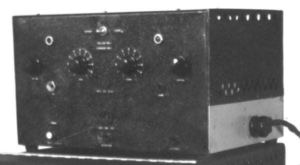
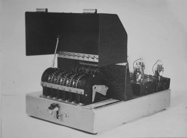
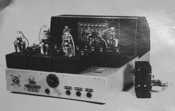
Delilah was a voice secrecy system produced at Hanslope Park by Alan Turing and a REME officer, Donald Bailey during 1943 and 1944. The units are a Key Stream generator, a combiner Unit, and a Power Supply. One of each was used at the sending and receiving end. The system works on mains electricity and is not very heavy so it can be moved around easily. The first official record that has come to light appears to have been a report dated 6th June 1944 in which Alan Turing wrote that research began in May 1943. A Combining Unit appears to have been in existence at this time but the ideas about the Key Stream were just coming together. The main report appears to be undated, but it must have taken many more months to build a Key Unit and carry out the reported tests and measurements. One might speculate that the project would have run until the end of 1944. What is common to many voice encipherment systems is a key stream that is unique for a given transmission. This is ideally in a ‘one-time pad’ form that is added at the send end and subtracted with an identical key stream at the receive end. It is believed that Alan Turing was shown under strict security the workings of an American Voice Secrecy system called SIGSALY when visiting the States (see en.wikipedia.org/wiki/SIGSALY etc.) and might have contributed to its design. SIGSALY systems were extremely large, about the size of a 1950s mainframe computer and extremely expensive. Even more expensive were the ‘gramophone records’ that held the unique key stream. These had to be distributed very securely to each end of the voice link and once used, destroyed. It is speculated but assumed that Turing thought that he could improve dramatically on this at a fraction of the cost. In Delilah his one-time pad was the setting of five letter transposition wheels like an Enigma Machine, plus a seven way patch panel. These modified the key stream. Not quite a one-time pad but as this key stream changed with every send and receive change, breaking an enciphered voice message that would change in minutes was considered at that time to be very secure. To add to this, wheels could be reversed, or alternatives fitted. As with Enigma the weak spot would be the ‘Wheel Setting Sheet’ which the enemy would wish to get hold of so that they could then decipher the messages. The system is labelled MK 1 with the report detailing the need for further development. No doubt this work could have continued but the war was being won and people were looking forward to a civilian career. From what we read about Alan Turing he was also very keen to get back to computing. As it was the system was not developed to the production stage but what was a technical advance was, the very clever method of producing a one-time pad that was thought to be highly secure in 1943-44. The technique bears some similarity to a German Enigma machine where every message/voice transmission is unique. The setting for a given message was secure for the time of a given ‘talk’ so long as it was longer than a few minutes. When the sender went from send to receive the key stream changed ready for the next unique transmission. The original Delilah Project came to the attention of the Bletchley Park Volunteers when one of our team, who regularly visits the National Archive in Kew, discovered a very large report. It consisted of 80 pages of text and formula plus circuit diagrams, blueprints, and oscilloscope images. We arranged to make copies of these using a camera. This was a start but later the GCHQ Archives department made available a full copy in much better quality than ours. We became quite excited about this project because it was a major piece of work carried out by Alan Turing. To be fair, Andrew Hodges had already ‘discovered’ the Delilah Project some years ago (Alan Turing – The Enigma – pages 273-276 inclusive). In this he writes about Don Bayley, Turing’s partner, and co-author of the report. Also, there is a picture and a brief reference by Dr. Robin Gandy in a BBC TV Horizon documentary directed and produced by Christopher Sykes some years ago. Although Turing was considered to still be based at Bletchley Park, he spent many months at Hanslope Park presumably because they had good workshop facilities away from the Hurly Burly of Bletchley Park. With the help of retired Hanslope Park Foreign Office staff we were able to track down Don Bayley who was then living quietly in Yorkshire. I have visited him there and since corresponded. No doubt the authorities were no longer keen to fund further, war-related, developments. Whatever the reason no further work was done on Delilah and it never went into production |
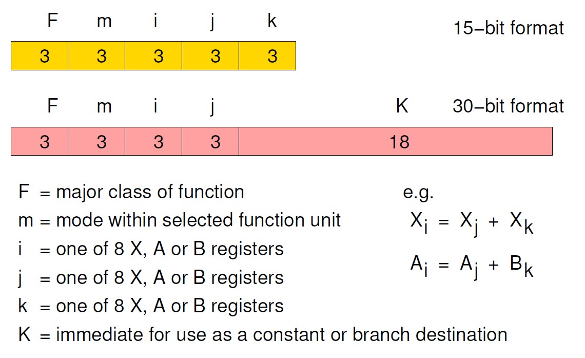
Simulation Modelling of Historical Computers[2]Roland Ibbett & David DolmanBeing part 2 of the article part 1 of which can be found in Resurrection 100. CDC 6600 The CDC 6600 was first demonstrated by the Control Data Corporation in 1964. The design team was led by Seymour Cray, who went on to design the CDC 7600 and later, after he left CDC to form his own company, the Cray-1. The 6600 was designed to solve problems substantially beyond contemporary computer capability. It achieved its performance by the use of parallel functional units, a small set of Scratch Pad registers, a three-address format (Figure 5) that allowed successive instructions to refer to totally independent input and result operands, instruction buffering and by off-loading peripheral handling to separate peripheral processors. Particularly interesting to students of computer architecture is the Scoreboard system used to control the operation of the parallel functional units..
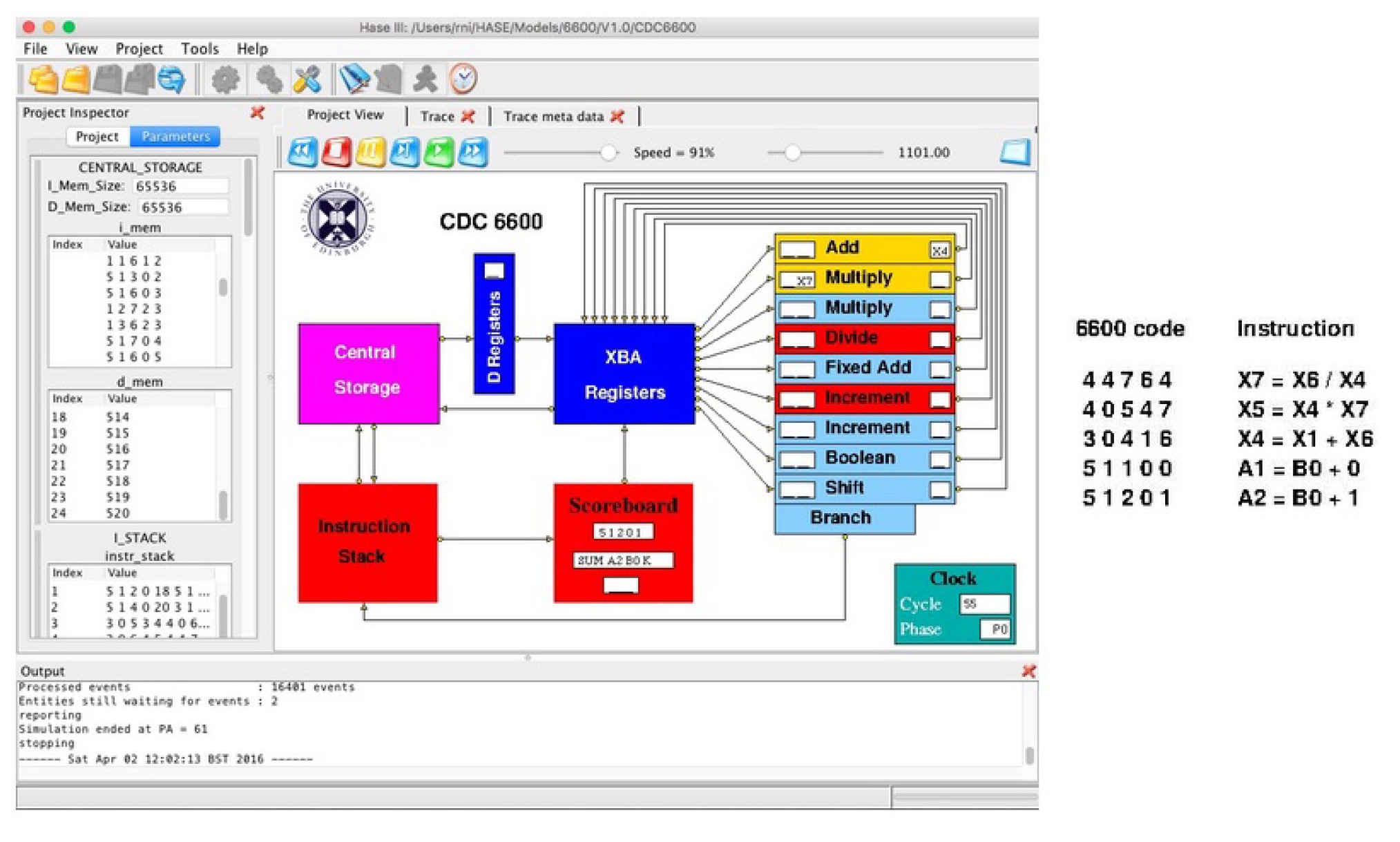
Figure 6 shows the HASE simulation model of the CDC 6600 during execution of the first of the two versions of the model available from the website. This version contains a program that demonstrates the operation of many of the CDC 6600 instructions implemented in the model. In particular, it includes sequences of instructions that show how the Scoreboard deals with instruction dependencies. The second version contains a matrix multiplication program that shows how the instruction stack works and how instruction unrolling of the scalar (dot) product calculation (the inner loop of matrix multiplication) is used to maximise register use.
In principle it ought to have been possible to represent the 6600 instruction set in the model using the INSTR construct but in practice there is no regular relationship between groups of functions and the register sets, so most instructions have to be decoded, and their registers selected, individually. Instructions are therefore represented using a STRUCT containing 5 integers and instructions are decoded in the Scoreboard simulation code using a switch statement. The code for each case in the switch selects the required registers and also contains text to be displayed in the Scoreboard icon showing the assembly code representation of each instruction. On screen, active entities (other than memories) are coloured red, inactive entities are shown in light blue, while entities that are held up waiting for a packet from some other entity are shown in yellow. In the functional units in Figure 6 the functional unit colours appear correspondingly as dark grey, light grey and white. Also shown on the right in Figure 6 are the instructions in the sequence currently being processed. The first instruction is being executed in the Divide Unit. The second instruction has been issued to the first Multiply Unit but cannot start because it is waiting for the result from the Divide Unit to be returned to X7, as shown by the entry in the window at the left-hand end of the Multiply Unit. This is known as a “second-order conflict” in 6600 terminology, but would nowadays be called a “read-after-write dependency”. The third instruction has been issued to the Add Unit, but cannot start because of a “third-order conflict” (a “write-after-read dependency”) on X4, as shown in the window at the right-hand end of the Add Unit, i.e. it is ready to write its result to X4, but the current value in X4 has not been sent to the Multiply Unit. The design of the 6600 was such that register values are sent to a functional unit only when both are ready, i.e. not waiting for a result from a previous instruction; here X7 is not yet ready. The next instruction does not depend on any previous results, so has been issued to the first Increment Unit and is being executed. The Scoreboard is displaying the last instruction, which is yet to be issued. The window at the bottom of the Scoreboard is used when there is a “first-order conflict”, either because the instruction about to be issued requires a functional unit that is already busy or because its destination register is already waiting for a result from another unit (a “write-after-write dependency”). The Manchester ‘Baby’
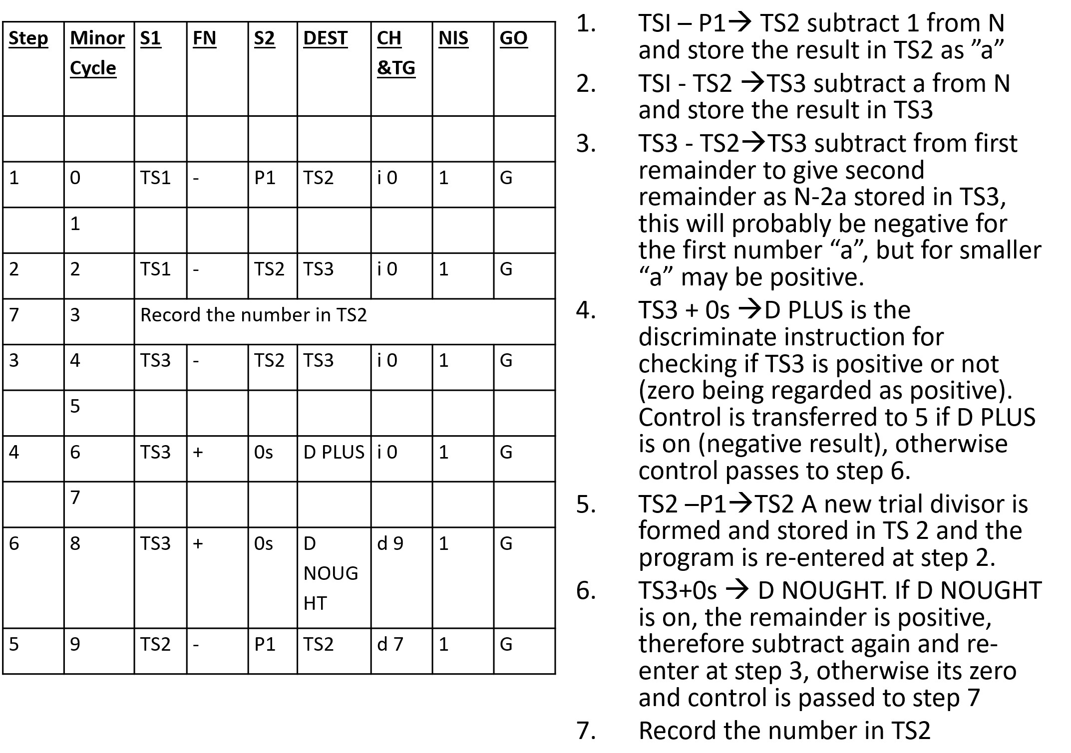
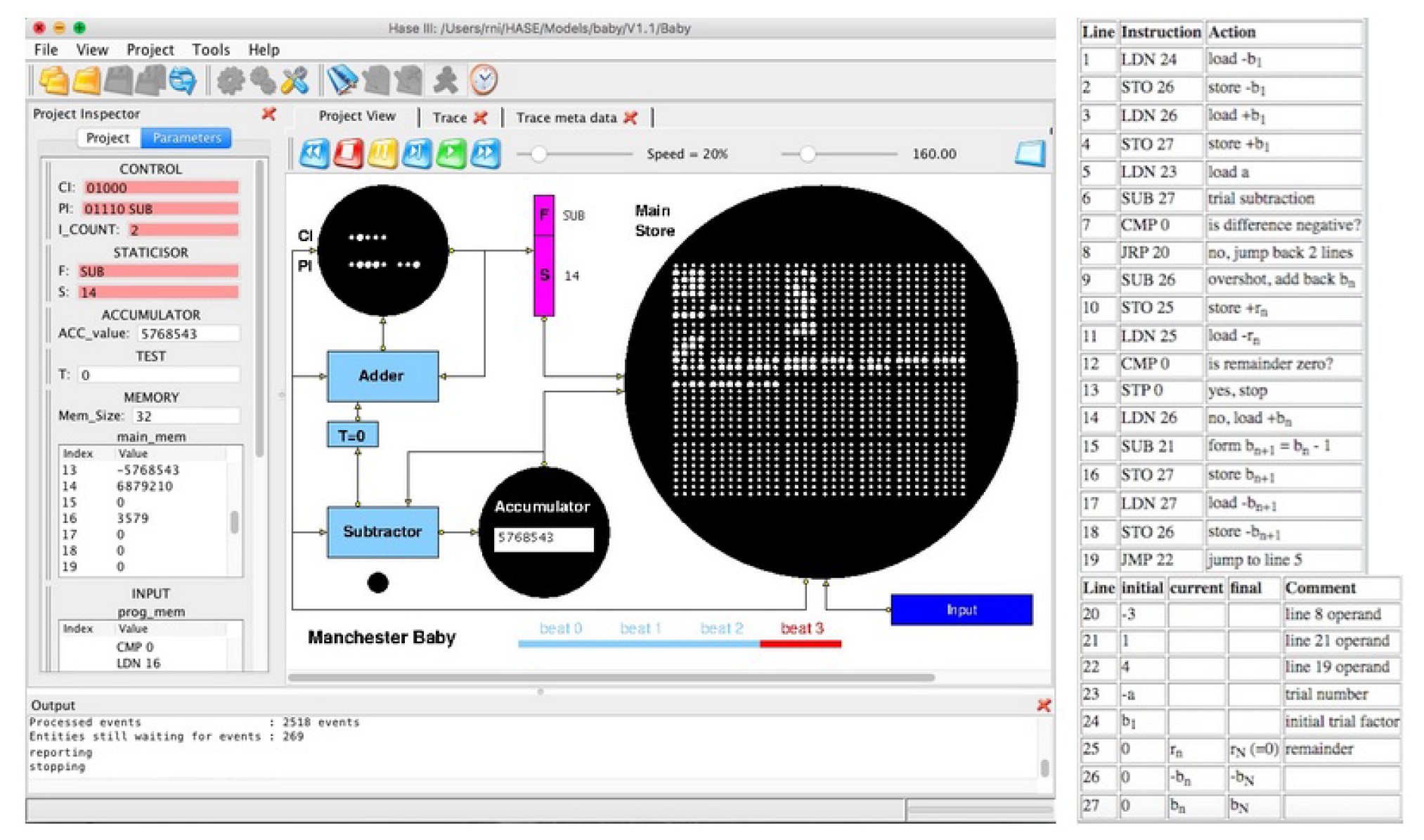
On 21st June 1948 the University of Manchester Small Scale Experimental Machine, affectionally known as the ‘Baby’, became the first computer to execute a program (Kilburn’s Highest Factor program) stored in addressable read-write electronic memory. This memory worked by storing charge on the screen of a cathode ray tube, now known as a Williams-Kilburn Tube. Like the Baby itself, the main emphasis of the HASE Baby model (Figure 7) is to demonstrate the operation of the Williams-Kilburn Tube Main Store. This requires its icon to be large enough to clearly display the Baby’s 32 lines of 32 bits each. To allow for this, the Accumulator and CI/PI icons are much smaller. In the case of the Accumulator a further compromise is that the value is displayed as an integer rather than a pattern of 32 dots and in the case of the CI/PI icon, only the relevant bits of the CI and PI words are displayed, i.e. 5 bits and 8 bits respectively. The PI bits are only visible whilst PI is in use. At the start of a simulation the program and its data are contained in two separate files held in the Input entity. In the current version of the model, these files can contain the code and data for four programs (there are currently three in the model). A parameter of the Input entity allows the user to select the program to be run. During the first clock period of the simulation the relevant sections of these two files are transferred into the Main Store entity. Entries from the program file are converted from the human-readable form in the input file into Baby format and transferred to the Main Store starting at location 1 (because the first action in the Baby was to increment the value (initially 0) in the CI register). The remaining Main Store locations are then filled with values from the input data file. Each word in Main Store is then displayed on the screen in focus/defocus format, with a small (focussed) dot representing a 0 and a large (defocussed) dot representing a 1, and with the least significant digit at the left-hand end. Reading a line in a Williams-Kilburn Tube involved writing a 1 to each bit location in the line. If the location contained a 0, there was a redistribution of charge on the screen and this induced a voltage in a pick-up plate placed close to the screen. If the location contained a 1, there was no redistribution of charge, so no voltage was induced. In the HASE model a line being read from the Main Store is shown changing to all 1s and then changing back to its original value, though this is purely a feature of the display; the Main Store array remains unaltered and is simply read by an assignment statement. A further difference between the model and the Baby itself concerns the way in which the serial nature of the Baby is visualised. Watching 32 bits transfer between entities at a rate of one per clock period would be extremely tedious, so words and addresses are each transferred in a single HASE clock period with their integer values represented by strings of 0’s and 1’s. The time taken to read a full word from the Main Store, plus the fly-back time, constituted a ‘beat’ of the machine. Four beats were required to execute an instruction. In the model these are: add +1 or +2 to CI, copy CI to staticisor read Main Store, send instruction to PI copy PI to staticisor, fetch operand from Main Store execute the present instruction The timing bar at the bottom of the Project View pane shows which beat is active as each instruction is executed. The black dot below the Subtractor represents the neon lamp that lights up when a Stop instruction is executed. Of the three programs contained in the model, Program 1 demonstrates the operation of all the Baby instructions, while Program 3 displays a simple message on the Main Store icon. Program 2, for which the code (in Chris Burton’s modern mnemonic version) and data are shown on the right in Figure 7, is the 18th July 1948 version of the Highest Factor program, as described by Geoff Tootill, along with some of his explanatory comments. The number under investigation, a, is set to 4537 (=13x349) in the input data file, this being one of the numbers used in the first tests of the Baby on 21st June 1948. The initial trial factor, b1, for that test was 4537 but in the model it is set to 360 to avoid a very long simulation run. At the end of a simulation run, the highest factor of 4537, 349, is in Line 27 of the Main Store. Of course users of the model can set the input values to numbers of their own choice. Conclusion Simulation models of historical computers that provide visual demonstrations showing how their various architectural features operated offer effective alternatives to preserving, in working order, what were in many cases very large pieces of equipment. Having simplified models in an application such as HASE allows anyone interested to down download a model and observe it in action. Future It is intended to update the text of this article from time to time as and when the system develops. Go to www.ccsoc.org/hase0.pdf for the latest version. HASE simulation models of a variety of computer architectures and architectural components have been created, some for research investigations of large-scale computing systems and others for use as teaching and learning resources in lectures, for student self-learning or for virtual laboratory experiments. The HASE website (www.icsa.inf.ed.ac.uk/research/groups/hase/) provides access to the models and to the Java code for HASE itself. Each model has its own supporting webpages describing the system being modelled, as well as the model itself, and from which the source files for each model can be downloaded. These files can be used as inputs to HASE, which has options to load a project, to compile a simulation executable and to run the simulation. Running a simulation produces a trace file which can then be used to animate the on-screen display of the model to show data movements, parameter value updates, state changes, etc. |
Contact details
Readers wishing to contact the Editor may do so by email to
Members who move house or change email address should go to
Queries about all other CCS matters should be addressed to the Secretary, Rachel Burnett at secretary@computerconservationsociety.org, or by post to 80 Broom Park, Teddington, TW11 9RR. |
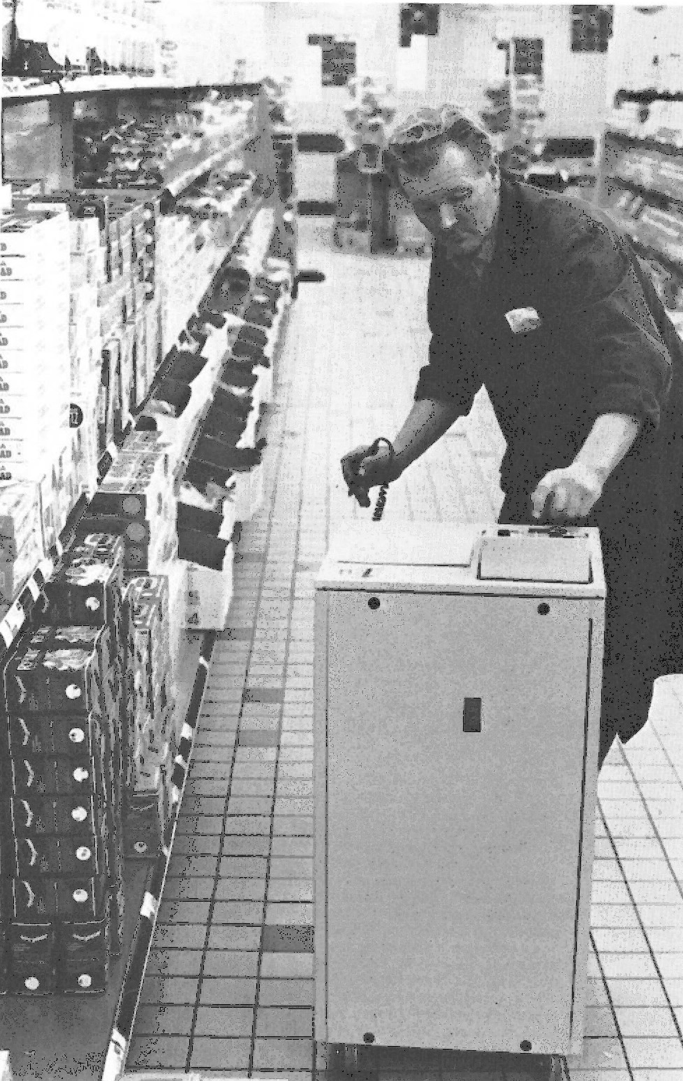
The Birth of the BarcodeDerrick BrownThis article covers the development of the world’s first barcode system to be used in a commercial environment. The problem that was to be solved is described together with the solution, in which the barcode played a crucial role. Although 50 years has flown past, elements of the system including the barcodes remain in use to this day. The two engineers carried a large heavy box and a bulky bag into the director’s office. They unpacked the contents revealing a plain steel box with a display panel and a dial-telephone cradle but without the usual telephone handset. Instead a largish tubular device that they called a ‘reading wand’ sat on the telephone cradle, connected by a wire to the box. This, they explained, could read a code made up of black and white stripes. A striped code was produced, about twenty centimetres long. The director and myself made up the audience. We watched as one of them wiped the wand across the coded stripes. The number represented appeared in the display. Another striped code was produced and wiped, with the number appearing in the display. Then another. Then the code was wiped backwards, the number appearing correctly. The audience was impressed. The director took the wand and wiped the code himself. “Of course”, he said, “they may receive rough treatment” and with that he vigorously wiped the wand back and forth across a code. There was a bang and a flash from the box and a pungent burning smell. “Oh well”, he said, “these things rarely work the first time!” Despite this little set-back he was sufficiently impressed to give me his support for on-going development and this led to the world’s first commercial barcode application. This event took place alongside the River Thames, in the Blackfriars, London Head Office of Sainsbury’s (JS), following some months of discussions and site meetings between myself and a small unit of the Plessey company, based at Poole, Dorset. This business had been behind one of about 60 responses from an enquiry that Sainsbury had put out for a proposal for a method of capturing data in remote locations. Most of the unsuccessful responses were fanciful, ridiculous, or pure science fiction. This was 1971 and data was collected by keying. Mark sensing was also being used in specialised applications but had severe limitations. Many of the solutions put forward relied upon keyed data, in some form or another. The solution from ICL, for example, involved mobile teletype terminals with trailing power cables – but the brochure was beautifully produced! I ruled this out along with all keyboard-based solutions. The requirements specification demanded a data collection system that was error-free, that could be used by anyone without training, with equipment that was easily portable by a person. But how had this come about, one may ask? Well, I had fallen on my feet. I had been running a project at Sainsbury’s to develop a system to produce the picking lists – the information for the distribution depots to assemble and transport goods to Sainsbury’s supermarkets. I had achieved this and the system was up and running on our recently-delivered ICL 1900 series computers which replaced two Emidec 1100 paper-tape machines – the last such working machines in the country. I had installed data transmission systems to transmit the picking lists from head office to each depot, using the STC GH210 off-line equipment, running on private telephone lines at 2400 bauds – the fastest then available. ICL had nothing to offer to achieve this. But Sainsbury’s – at the time the biggest supermarket group in the UK and the retailer with the highest turnover per square foot of selling space in the world – had a problem. It was not a new one. All retailers need to have control of their stock so as to not have too much stock, as it tied up capital and space, but with a minimum of out-of-stock items. Getting this balance right was the key and the current system at JS was not working. The amount of each item delivered to the stores each week was calculated by the large, central computer system, based on the previous sales and the current stock. The latter had to be counted laboriously by the supermarket staff, sent to the head office in London where the computer went through its complicated mathematical routines to produce the forecast requirements for the following week. The requirement – e.g. a number of packs of item xxx, say, baked beans, 10oz, in a pack of 24 tins to a pack – was calculated for every product, in each of the supermarkets. Not only that but that xx packs would be sent on say Tuesday and yy packs on Friday. Fine, but the forecast was invariably wrong and the delivery dates were often too early or too late. Stores were overstocked on some things and out of stock of others – for days. There can be no perfect forecasting system that copes with real life. For years the forecasting system had been tweaked by experts and used the Box-Jenkins factors among other routines. But the system never was, and never could be, satisfactory. The supermarket managers had no power or ability to do anything. Each supermarket had a backroom stock, and stock had to be moved from there to the selling area. Sometimes stock would be in the backroom but couldn’t be found and was not available on the shelf. Customers get upset when products are not available, and Sainsbury’s board was very sensitive to customers’ demands. A new system was desperately required. A high-level committee was formed and I was appointed as the I.T. representative. I was the most junior, being the only non-senior manager/departmental director on the committee. Meetings were held and much head-scratching went on. Visits were made to Europe and the USA in the search for ideas. There was nothing that could be found that solved the problems. Eventually a ‘dream solution’ was described. Firstly, all the stock would be on the supermarket shelf – no backroom stock at all. This meant that the huge job of moving stock around would be obviated. A shelf space would be allocated for each product, based on an average two-days sale (this was smaller than that then used). At the end of each day’s trading, the staff would assess how much of each product was required to fill the hole now in the shelf space. This information would be sent to the head office and the requirement would be processed and sent to the distribution depots, assembled, loaded onto trucks and sent out overnight to arrive at the supermarket the next day. Staff would move the stock straight from the truck to the shelf. These days it would be called a ‘just in time’ system, then it was just a dream! If it worked the supermarket need never be out of stock as long as the distribution depot had stock, and there would be large savings in labour – no movement of stock from backroom to shelf. The main advantages would be reducing out-of-stocks and improving Sainsbury’s reputation but it was realised that another advantage was there for the taking. Sainsbury’s was so successful that a common complaint was overcrowded stores. If the stock backroom could be eliminated, then this space could become selling area! The required system logistics were challenging to say the least. There was nothing on the market remotely suitable to capture data in several hundred remote locations, quickly, without error, and with the capability to transmit the data to the head office. There would be 250,000 item orders per day, and this was planned to increase dramatically. Even an error rate of 0.001% would result in a number of lost orders. Hence the call to companies and private inventors and the demonstration of the ‘breadboard’ model. Perhaps surprisingly, there were a number of vocal objectors to the proposed barcode idea. It was new, unproven, and the equipment to make it useable didn’t exist. I saw it immediately as a solution, if not the solution. Perhaps my enthusiasm backfired. I had arranged the demonstration as a means of getting the I.T. director on-side, and it worked. I led an initial team of two systems analyst-programmers, although this quickly grew. A pilot system to test the basic philosophy was set up with a crude card system to collect data with supermarket staff calling out the results on a voice telephone to head office staff, who then completed a mark-sense card for input to the depot picking system. This proved that the basic idea of ordering sufficient product to fill a hole in the supermarket shelf actually worked, and that it was easy to provide sufficient information for anyone, with hardly any training, to assess the requirement. Suddenly the store could order products that were needed, deliveries were made within hours, and the shelves were re-stocked. Despite the drawbacks of the very basic system that we had put in place the board of directors was delighted with the results and demanded that we immediately expand the system to more supermarkets! I resisted this proposal, saying that it was a side show and would deflect us from the main game, but not surprisingly lost the argument. At one time we had 16 telephone operators at head office taking down the data from 70 supermarkets. It also was the means of establishing the changed distribution processes which was quite challenging for the depot management. In the meantime we were searching for the data collection solution
At this time several companies had been trying to develop a successful barcode reading system. Several attempts had been made with no great successes and in 1971 there were no systems on the market. It wasn’t until 1973 that the Universal Product Code was agreed upon using an IBM barcode design but the uptake was slow. By 1977 there were only two hundred stores in the USA using the UPC codes as suppliers were slow to co-operate by printing barcodes on products. However, the UK Plessey company had developed its own two-bar code design earlier but had found no takers for it ... until Sainsbury’s came along in 1971. They hadn’t really any idea what to do with it, hence the reading ‘wand’ was on the cradle of a telephone handset, along with a dial! Yes, they could replace the dial with a keyboard, and yes, the barcode could be reduced in size. The barcode and the reading wand were reduced in size, the code could be read in either direction and reading tests showed that errors were so few, because of the cyclic redundancy check employed, as to be non-measurable. I wanted belt and braces though, so we introduced a further check – a modulus eleven check digit on the stock number that we would be using. As there was no printing process that we could acquire we had to purchase the barcodes then allocate them to the stock units, rather than using the Sainsbury’s standard I.D. system. Over the first several years of operation with many millions of barcode readings we never detected any reading errors. The data, once read, had to be recorded and a mini-cassette was used for this. Power was a problem as there were no small batteries available to do the job. Two lead-acid car batteries were used at first so making the portable device a rather clumsy trolley. The NASA space programme soon resulted in smaller batteries so it wasn’t long before the mark 2 unit appeared – a satchel unit. When lithium batteries became available the mark 3 unit became a hand-held device.
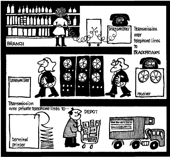
Plessey designed the unit to suit our requirement and designed a transmitter to be used in the supermarket to transmit the data over the standard telephone network. The transmission was sent when the head office called up the unit and response from the supermarket was all automated. At head office a receiving unit dialled the supermarkets, collected the data and created a standard magnetic tape that was transferred to the ICL computers running the picking list system. Each supermarket was equipped with two data collection devices and one transmitter. All the staff had to do was to plug the collection devices to the transmitter. Nothing else, so nothing to go wrong, but see below! Answering the phone, switching on, tape re-winding, sending the supermarket id (very important) was automated. Each transmission took a couple of minutes. As more supermarkets were switched to this system the calling up operation at head office was also automated, using a front-end processor that auto-dialled the supermarkets using 32 lines. The very first supermarket to trial the system was a north London store in Islington. Barcodes identified every product place on the shelves. A part-time shelf filler was briefed and sent to assess what was required and capture the data. He achieved this without any questions or delays. The trial went on for some weeks and it did produce a problem that took a while to solve – sometimes part of the order was not transmitted. It was caused by static – when the trolley was wheeled close to a cooler cabinet a spark sometimes jumped as the trolley earthed to the cabinet. The spark produced a signal – a ‘rewind tape’ signal so all orders recorded to that point were lost! It had us all scratching around for some time before we found the issue. Another time a cleaner unplugged the transmitter to plug in her vacuum cleaner so the store unit was unplugged and could not respond to the head office call! These issues were quickly fixed and the system was an outstanding success, with stock-outs being virtually eliminated, stockholdings reduced and labour costs radically reduced, even more than had been anticipated. So in August 1972 an article appeared in The JS Journal – the company house magazine – that described the system that by then had been installed in 30 supermarkets and was rapidly being installed in a company-wide programme, overall 250 supermarkets. It was described by the company Managing Director, Mr J.D. Sainsbury as the greatest step forward that the company had made in its more than 100 year history, even more significant than the change from counter-service to self-service! It took more than two years to prepare, equip and switch all the supermarkets to the new system. The directors then demanded that all product groups be included, not just the 2000 grocery products. These other groups had special requirements and the system was slowly extended to accommodate these. And today, 50 years later, you will still see shelf barcodes in every Sainsbury store, now numbering more than 1,000, identifying up to 10,000 products in each. Not to mention their appearance in almost every other walk of life! At the time the application described here made quite an impact so that I was invited to give a number of presentations to interested parties, firstly to branches of the BCS then further afield. The UK retail trade picked up on it with presentations in London, followed by international conferences in Amsterdam and Paris. So who would have thought it? A piece of technology still being used, no, seriously embedded, in today’s society, after 50 years! Is there anything else connected to the computer industry that is still in use after this long? Millions of barcodes are read around the world every hour of the day. And the first ones were installed and working in the U.K in 1972! So 2022 was the Golden Jubilee of the barcode! A CCS seminar on this matter was given in January 2023. Go to ccsoc.org/jsbc1.htm where a link will be found to a recording of the event. This article is also scheduled to appear in a forthcoming edition of IT NOW. Derrick was born in London and lives in Melbourne, Australia. He joined J Sainsbury where he worked from 1969 to 1976 in systems development. He then became Information Services Manager for Plessey at its Ilford head office from 1976 to 1979, running a profit-centre computer services business. Derrick is long retired. He has authored “An Unexpected Development” Austin Macauley Publishers – ISBM 9781787100398 (paperback) / ISBM 9781787100404 (e-book). The contemporary article he wrote for JS Journal can be found at ccsoc.org/jsbc0.htm. |
50 Years ago .... From the Pages of Computer WeeklyBrian AldousEurope’s Met Centre in the UK: A £9 million weather centre equipped with a giant computer will be established at Shinfield Park, near Reading, following a decision on the siting of the centre, taken in Brussels on March 5th by representatives of 19 countries which have agreed to cooperate in scientific and technological research. When fully operational the centre will undertake medium term – four to 10 day – forecasts on behalf of the 19 countries, providing estimated savings of £80 million a year for those throughout Europe whose business is weather dependent. The centre will be an independent body, administered by the EEC Commission, but initially, for a transitional period of two or three years, it will rely heavily on support provided by the Meteorological Office at Bracknell which is equipped with a 360/195. According to Mr Patrick Meade, director of services at the Met. Office, the centre will be accommodated in the Bracknell area while the necessary buildings are being erected at Shinfield Park. During this period staff of the new centre will have access to the Met Office’s 360/95 and will make use of its worldwide telecommunications system. Mr Meade told Computer Weekly that the centre would require a far more powerful computer than that currently installed at the Met Office. Studies carried out by the European countries suggest that a system capable of carrying out 50 million instructions per second will be required. This compares with the eight to 10 mips capacity of the 360/195. (CW 15/3/1973 p1) ICL launches addition to Key-Edit series: : A new key-to-disc system which is available with as few as four keystations at a rental of £370 a week has been introduced by ICL. It is a member of the Key-Edit series to be known as the Key-Edit 50. Like its bigger brother, which will now be known as the Key-Edit 100, it uses a PDP-8/E as the central processor, but with a maximum of 24K core. The major new feature is re-designed software, a necessary requirement if the core maximum was to be adhered to. One result of this is a multibatch grouping feature, said to be unique to the new system, which enables the supervisor to group up to 200 batches of the same type. The supervisor can list them, write them to tape or delete them with one command instead of 200. A basic Key-Edit 50 system comprises processor, memory, fixed head disc of 1.4 million characters capacity, a magnetic tape unit of 556 or 800 bpi, a supervisor console and four keystations. (CW 29/3/1973 p1) ) In-store PoS system installed: : With the opening of the new Bentalls department store at Bracknell. Berkshire, NCR has installed what it claims to be the first complete “in-store” point-of-sale terminal system in the UK. As reported exclusively in Computer Weekly, Bentalls has opted for the NCR 280 retail terminal and 45 of these units, together with two NCR 723 data collectors, have been installed. At present, sales data collected by the system is processed at an NCR computer bureau in London, but Bentalls has plans for an in-house computer, likely to be an NCR machine, before the end of year. The terminals, which each have a 512 byte memory, are programmable to enable a company’s specific transaction requirements to be handled. Also incorporated in each terminal is a small display screen, a magnetic tape cassette unit, a receipt printer, and a sales bill printer. It is anticipated that light pens will be used in the near future to read tags and labels marked with bar codes. This will enable management to obtain a more detailed sales analysis than at present possible. (CW 12/4/1973 p17) ) Automation plan for local radio station: : The London commercial radio station, Capital Radio, which is due to take to the air within the next 12 months as a general entertainment channel, is finalising negotiations with EMI for an automation system worth more than £20,000. Capital is acquiring an EMI 903 system equipped with a solid state direct access memory which can be directly interfaced with either a computer or teletype system. The 903 can provide a full 24 hours of continuous broadcasts – the memory being programmed to select on a time or sequential basis pre-recorded material. The operator, using a 16 position keyboard, can insert a complete broadcasting programme for a day in the memory, building it up on a minute by minute basis if required. EMI says that the 903 can be equipped with a plain language logging system which automatically produces a printed record of an entire broadcast schedule after transmission; this is considered particularly useful to verify the transmission of commercials. The system will cue all random access devices in advance by searching the programme time-file for up to six hours ahead of the material currently playing. (CW 19/4/1973 p3) ) 2903 spearheads ICL’s drive to win new markets: : As first predicted in Computer Weekly on March 15th, ICL have launched an important new product aimed at the lower end of the market which, although compatible with the 1900 series, is eventually likely to become part of the New Range product line. Called the 2903, the new system. which is to have its first public showing at Hanover Fair which opens today, is a microprogrammed “soft machine” that currently looks like a 1900 Series system. It is disc-based, has video operator’s console and direct data entry capabilities, provides IBM compatible RPG2 as the main software language, as well as COBOL and Fortran, and has a wide range of applications packages available, including bill of materials, order entry, stock control. Pert and Prosper. (CW 26/4/1973 p1) ) Logica to sell ARPA know-how: : Access to the expertise which has gone into the development of the ARPA network – the world’s most advanced computer network – will become available, at a price, to European organisations. It follows an agreement between Logica with its French associate, SESA, on one hand and Bolt, Beranek and Newman Inc, on the other. BBN, a US consultancy with a great deal of know-how in the communications field, has been involved in the four-year-old ARPA project virtually since its inception and has been responsible for development of the communications protocols and the Interface Message Processor (IMP) and Terminal IMP (TIP) packet switching systems, on which the network is based. The network, which has been developed by the Advanced Research Projects Agency of the US Department of Defense, currently links more than 40 large and medium sized computers installed throughout the US, at sites such as MIT, Harvard, NASA’s Ames Research Centre – home of ILLIAC IV – Stanford Research Institute and the Rand Corporation. An offshore link to Hawaii has also been established and agreement has been reached on the establishment of a link to Norway with a connection to London University’s Institute of Computer Science. Under the new agreement Logica and SESA will have access to BBN’s communications know-how. Consultants from both companies will spend several months with BBN at Cambridge, Massachusetts, familiarising themselves with BBN’s work on the ARPA project, possibly studying future developments such as the transmission of data via satellite and the further enhancement of IMP and TIP systems. (CW 3/5/1973 p1) ) Banks sign for SWIFT service: : The international banking message switching network, SWIFT, achieved official status last week in Brussels when 240 leading banks in 13 countries from Europe, Canada and the US became founder members of the non-profit-making Society for Worldwide Interbank Financial Telecommunications. Based on switching centres in Brussels and Amsterdam with concentrators in 14 other countries, the SWIFT network will provide its members with a private international telecommunications network which will enable the banks to transmit international payments, statements and other related messages. The objective of the new service, which is scheduled to become operational in 1976, is to provide more convenient and reliable transmission capabilities than mail and telex facilities and to make possible reductions in the banks’ message handling and processing costs by the introduction of a number of measures of standardisation. (CW 10/5/1973 p1) ) Greater London Council extend London traffic control system: : As a further development of the GLC’s traffic control system, an additional 200 signal intersections are to be controlled by next March, extending the area of the system radially outside its present approximate boundary marked by a line linking the main London railway termini. The system has been operating since mid-1972, following a pilot project covering 70 signals in West London, starting with 23 signals in the Baker Street and Marylebone area. Computers for the system were supplied by Siemens under a £759,000 contract awarded in 1970 against two British tenders from Plessey and GEC-Elliott Traffic Automation. Two Siemens 306 computers, one with 32K and the other with 48K of core, were installed in 1972 at the GLC’s offices in County Hall. Both machines have now been moved to a new traffic control centre at New Scotland Yard, and the 32K 306 has been enhanced with a further 16K of core. In addition, a further four Siemens 81/52 display consoles are being installed. Work by Siemens is being carried out under the terms of the initial contract, which also planned for the control of 1,070 of the 1,500 traffic signals in London by 1976. Environmental control for a new computer suite at New Scotland Yard to house the Siemens system is being provided by Precision Air Control Ltd under a £33,000 contract. (CW 17/5/1973 p20) ) Memorex launches floppy disc drive: : A new OEM floppy disc drive, the 651 Flexible Disc Drive, has been announced by Memorex UK Ltd. This is an improved version of the 650 which was announced last year but was never strongly marketed. The improvements include a faster track-to-track access time of 10 milliseconds, with 10 milliseconds settle time. The average latency time is 80 milliseconds, and the transfer rate from unit to unit, 250 kilobits per second. Another new factor is the FD/IV extended life disc, giving a minimum life of 50 million passes, evenly distributed. Data can be written in either sector or index mode, starting with 132 byte records with 32 records per track (on 64 tracks), up to one record of 4,880 bytes per track, giving a maximum capacity of 312,500 bytes or 2.5 million bits. Applications envisaged include auxiliary storage, remote terminal data acquisition, data logging, key-entry recording, point-of-sale recording, accounting machine storage and programmable calculator storage. Other uses are as a microprogram loader in writeable read-only memories, and as a diagnostic program loader. (CW 17/5/1973 p20) ) Calcomp launches Model 7000 flatbed plotter: : A new flatbed plotter, the Model 7000, has been introduced by Calcomp Ltd as the most sophisticated system in its range. The company says it will provide drawing quality comparable to that of a skilled draughtsman at speeds of up to 42 inches per second, with a resolution of 0.002 inches. To overcome the problem of quality as good as that done by generating lines of constant width and ink density, a new pressure inking system using four pens has been developed. The four pen reservoirs have separate air pressure tubes. An electromechanical system senses plotter speed and regulates the pressure to each pen as a function of plotter speed. The pressure ranges from a vacuum to one high enough to provide uniform lines at 42 inches per second diagonally on paper or synthetic materials. The operator can select from a range of performance modes by a simple cartridge load. If he has a good tape, the quality mode assures him of line quality as good as that done by hand, or alternatively, the performance can be adjusted to suit scribing or film cutting. The operator can scale the plot by factors of 2, 1, 0.5, 0.25 and 0.125. (CW 1/3/1973 p5) |
Forthcoming EventsMembers and others are welcome to attend CCS Seminars but these are also available via Zoom. London Seminar Programme
London meetings take place at the BCS — 25 Copthall Avenue Moorgate EC2R 7BP starting at 14:30. The venue is near the corner of Copthall Avenue and London Wall, a three minute walk from Moorgate Station and five from Bank. You should use the BCS event booking service to reserve an in-person place at CCS London. Go to www.computerconservationsociety.org/lecture.htm . The service must be used for remote attendance. For queries about meetings please contact Roger Johnson at meetingssec@computerconservationsociety.org Manchester Seminar Programme
Manchester meetings take place at The Manchester Metropolitan University, Chester Street, Manchester, M1 5GD – Room E0.07 in the John Dalton East Building starting at 18:00. Details are subject to change. Members wishing to attend any meeting are advised to check the events page on the Society website.
MuseumsDo check for Covid-related restrictions on the individual museum websites.
SIM : Demonstrations of the replica Small-Scale Experimental Machine at the Science and Industry Museum in Manchester are run every Wednesday, Thursday and Friday between 10:30 and 13:30. Admission is free. See www.scienceandindustrymuseum.org.uk for more details. Bletchley Park : daily. Exhibition of wartime code-breaking equipment and procedures, plus tours of the wartime buildings. Go to www.bletchleypark.org.uk to check details of times, admission charges and special events. The National Museum of Computing At present opening days are somewhat irregular so see www.tnmoc.org/days-open for current position Situated on the Bletchley Park campus, TNMoC covers the development of computing from the “rebuilt” Turing Bombe and Colossus codebreaking machines via the Harwell Decatron (the world’s oldest working computer) to the present day. From ICL mainframes to hand-held computers. Please note that TNMoC is independent of Bletchley Park Trust and there is a separate admission charge. Visitors do not need to visit Bletchley Park Trust to visit TNMoC. See www.tnmoc.org for more details. Science Museum : There is an excellent display of computing and mathematics machines on the second floor. The Information Age gallery explores “Six Networks which Changed the World” and includes a CDC 6600 computer and its Russian equivalent, the BESM-6 as well as Pilot ACE, arguably the world’s third oldest surviving computer. The Mathematics Gallery has the Elliott 401 and the Julius Totalisator, both of which were the subjects of CCS projects in years past, and much else besides. Other galleries include displays of ICT card-sorters and Cray supercomputers. Admission is free. See www.sciencemuseum.org.uk for more details. Other Museums : At www.computerconservationsociety.org/museums.htm can be found brief descriptions of various UK computing museums which may be of interest to members. |
North West Group contact details
|
||||||||||||
Committee of the Society
|
Computer Conservation SocietyAims and ObjectivesThe Computer Conservation Society (CCS) is a co-operative venture between BCS, The Chartered Institute for IT; the Science Museum of London; and the Museum of Science and Industry (MSI) in Manchester. The CCS was constituted in September 1989 as a Specialist Group of the British Computer Society (BCS). It thus is covered by the Royal Charter and charitable status of BCS. The objects of the Computer Conservation Society (“Society”) are:
Membership is open to anyone interested in computer conservation and the history of computing. The CCS is funded and supported by a grant from BCS and donations. Some charges may be made for publications and attendance at seminars and conferences. There are a number of active Projects on specific computer restorations and early computer technologies and software. Younger people are especially encouraged to take part in order to achieve skills transfer. The CCS also enjoys a close relationship with the National Museum of Computing.
|
