4.2
SELECT and
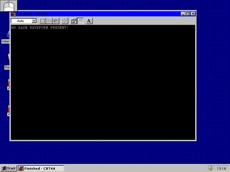
CLICK on "Crt4".
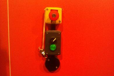
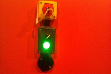
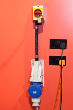
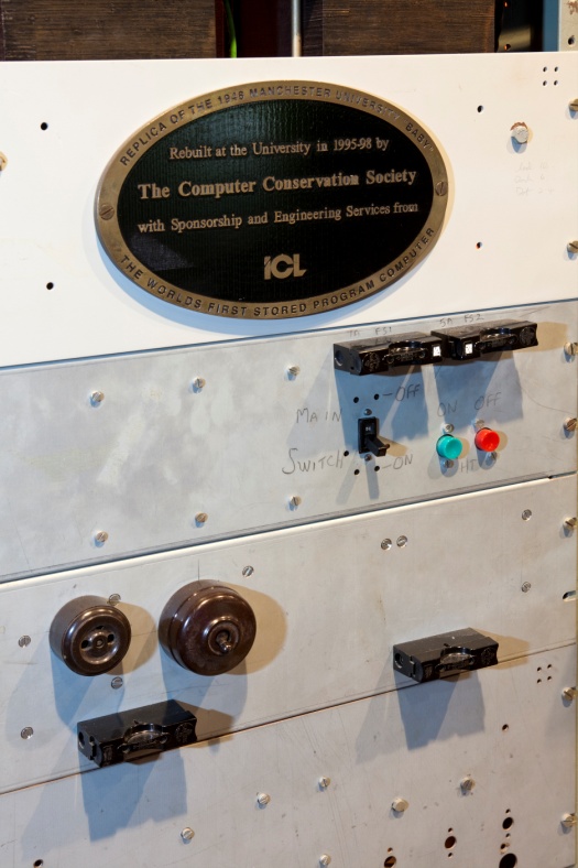
Power Control Panel
These should contain a list
of specific actions, and be periodic (e.g. hourly, daily, weekly etc.)
Ø
Use normal operation of the computer as a working check. If anything does not work normally, make a
note in the logbook, to be repaired by the ‘Baby’ technical team. Diagnostic and repair techniques are outside
the scope of this log.
7 Defect Notification
Use the operational log to
record defects/faults in the Baby computer log book and issue a report email to
the team.
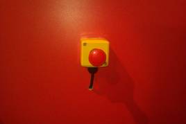
If major issues arise, e.g.
smoking parts ,switch off immediately, and put a notice on the main break switch to alert
others and notify the Curator..
8 Decommissioning
Object Name: Re-built ‘Baby’
computer
Accession Number: S23/1998
Likely cut-off date: 2048 or
later
Reason for Decommissioning :
Non-availability of parts
and/or limited technological lifetime of parts
9. Type History
The World's First
Stored Program Computer,
developed at The
University of Manchester.
[This is to serve as a reminder. You should aim for delivering the history in a
maximum of 10-15 mins. You may want to
start by making a connection between the main component parts of a modern
computer and the Baby. The amount of
detail you provide will depend on your audience.]
Before the 1930s, a ‘computer’ was a person who did
calculations, whether using a pen and paper or a mechanical calculator. The person decided what calculations to carry
out and in what order.
People have used calculating machines for hundreds of
years, such as the abacus. Bank workers
at the end of the nineteenth century needed to add up large quantities of
figures and mechanical calculators were developed to meet this demand. An example is the calculator in the case by
the text panel. There are more examples
of calculating machines in the Computers Gallery in the Electricity
Gallery. In the 1930s, Alan Turing
worked on a simple, general purpose, computer.
He developed a mathematical proof that it was possible but, as no reliable
store for data or programs existed, he could not turn the idea into reality.
After the end of the Second World War, there were a
number of groups, in this country and the United States, working on an
automatic computer. One of the groups
was working at the Telecommunications Research Establishment (TRE) and included
Freddie Williams and Tom Kilburn who managed to store information on a cathode
ray tube (CRT). [Show the example of a CRT].
Williams moved to the University of Manchester and seconded Kilburn to
help him develop the design.
Williams brought in other people to help, including
Geoff Tootill. In 1947, the group
succeeded in storing 2000 bits and published a paper describing this, but was
unsure if it would work in a computer because of the speed things changed. They decided to build a small-scale
experimental machine (SSEM) and began work in 1948, completing in June. They used the computer for mathematical
problems, such as prime numbers. At this stage it was known as ‘the machine’ or
as the ‘SSEM’. Later, once there was
another computer, it was referred to as the ‘Baby’.
On June 21, at approximately 11.15 in the morning, the
program worked correctly for the first time.
It produced the right numbers and Kilburn did not believe it. He and Tootill ran the program again and the
computer produced the same answer. They
fetched Williams to show him and then went to the pub to celebrate.
The computer you see here is a re-build of
the original which ran in June 1948.
That one was improved and enlarged into a full-sized computer, known as
the Manchester Mark I, in 1949. The
local electrical engineering company, Ferranti, re-engineered the computer and
delivered the first Ferranti Mark I to the University. The Manchester Mark I computer was scrapped
and the parts re-used.
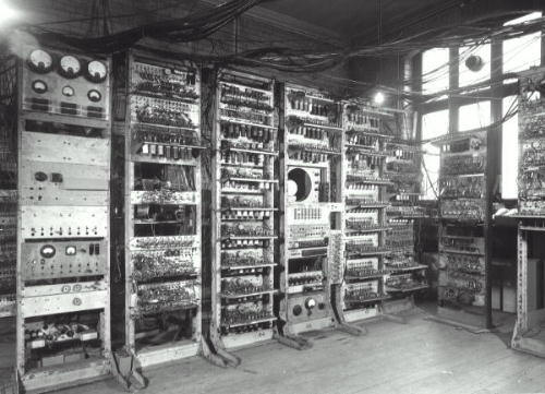
The original ‘Baby’ from a
photograph taken of the enlarged
Manchester Mark I in December
1949
10.
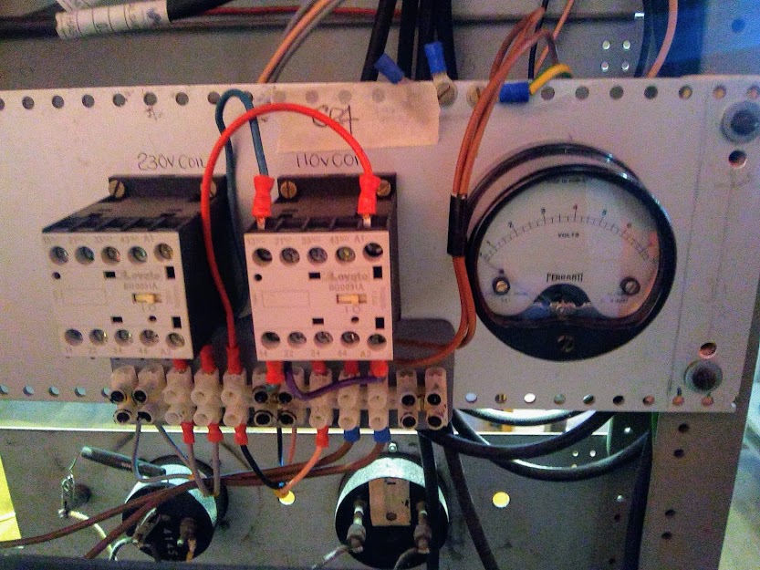
Technical Information - Digital
Storage – three cathode ray tubes
Accumulator: - accumulates the results of arithmetic
operations via the Subtractor.
- 1 word of
32 bits
Control: - 2 words of 32 bits. Controls
the extraction of instructions from the Store.
- CI (Control Instruction) - store address of Current Instruction
- PI
(Present Instruction) - buffer store for the Current Instruction.
Store: -
Holds instructions, starting values, and results, for the program.
- 32 Words 0f 32 bits (1024 bits; millions of bits
on today's chips!)
The Electronics
The team used technology developed for World War 2 radar and
communications equipment. The major components comprised 300 thermionic diodes
(EA50), 250 thermionic valves (mainly EF50 and EF55 pentodes)
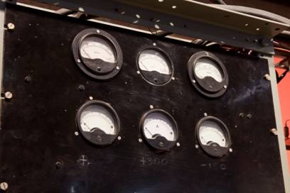
Power supplies: +300V,
+200V, +50V,-150V, -1250V.
Power consumption: 3,500
Watts.
Clock Rate: 100
kHz (330 MHz in today's PCs)
Physical
Size :- 5.23m (17 ft)
long, 2.26m (7ft 4in) high Weight :-
[metric equiv.](1 ton)
Programming
There were just seven instruction types. Programs were loaded bit-by-bit
using the push-button 'typewriter'. The first program was a test for prime
numbers, and could run from seconds to hours, according to the size of the
trial number. The historic first run took just a few seconds.
11. History of
Object before entering the Museum
The Computer Conservation Society
was formed in 1989 to promote the conservation of historic computers, develop
awareness of their importance, and to encourage related research. In 1995, Chris Burton, one of the Society’s
members, drew up plans to reconstruct the original 1948 computer for the 50th
anniversary. He put together a team to
work on the project and ICL agreed to sponsor it. The Computer Science Department at the
University of Manchester also provided space for the team to work in the early
part of the project.
The team was able to identify
parts from photographs but, as the photos were taken in December 1948, they had
to extrapolate back from there to June.
They also used the few circuit diagrams, drawn by newer members of the
original team as they joined, to put together drawings and reconstruct
layouts. The team obtained the parts
from warehouses of ex-MOD material and radio amateurs. Many of the valve cartons carry dates of
manufacture [show valve 1943]. Some must
have been carried by wartime Atlantic convoys. Valves were still being made until the 1960s,
which are probably more reliable than the older valves. The post office racks came from a BT
exchange, which was closing, and from someone’s garden where they had been
holding up the lawn from the river. The
resistors and capacitors were the hardest to find and came from individuals’
personal supplies. The values of many
had changed with age. The team then
began assembling the chassis.
In 1997, the team was able to
connect up the chassis and began testing and getting the machine to work. They added three dummy stores to enable
operation of the machine without using the main store. They used a PC to load programs into the
store and for testing. The PC [round the back] has been kept to download
programs quickly but this does not affect the way the computer operates. In February 1998, ICL moved the computer to
the Museum. In June, the University, the
City Council and the Museum held celebrations and, on Sunday 21, Tom Kilburn
and Geoff Tootill ran the original program again. The University also ran a programming
competition on the Internet for people to write programs for the Baby machine
for which they had 129 entries.
This rebuild has been made as
close to the original as possible.
Indeed, Tom Kilburn has said on several occasions that he cannot find
any differences, other than that it is not dirty enough! The original was sensitive to outside
interference and certainly had problems when trams went past. In order to avoid potential problems with the
rebuild, the team put in screening. The
wiring on the rebuild is plastic, whereas that on the original was rubber. Any changes made to the original design have
been described and explained in the documentation which accompanies the project
[to be deposited at the Museum].
12. History of Object since entering the Museum
The computer was moved in to the Museum by computer
engineers from ICL in February 1998. The
re-build team then spent time in re-wiring and checking the operation of the
machine in order to ensure correct operation for the 50th
anniversary of the running of the first program on 21 June. In the event, the main store failed, but the
team were able to run the program via the dummy store which substitutes for
that CRT and amplifier. Location
references for details of modifications etc. to be collected in appropriate
formats, e.g. printed, manuscript or oral history recollections.
Since June 1998, the team has made the following
modifications:
Ø
added remote control unit behind the key switches, driven by the PC
not operable curremtly
Ø
PC used for loading programs
Ø
installed a big heaters variac to give a progressive heaters-on action
13. Additional Interpretive Information/Sources
Small Scale Experimental Machine
Volunteers -
List of Books, Audio and
Internet Resources
Books on History
*1.M Campbell-Kelly, ICL: A Business and Technical History, Oxford University Press,
1990.
Covers more than the title suggests, since ICL’s
origins lay in the punched card era.
*2.Charles & Ray Eames, A Computer Perspective: a sequence of 20th century ideas, events and
artefacts from the history of the information machine, Harvard University
Press, 1973.
Based on an exhibition assembled for IBM.
*3. J Hendry, Innovating
for Failure: government policy and the early British computer industry, MIT
Press, 1990.
Examines the role of the NRDC in the computer
industry. With Campbell-Kelly’s ICL,
this provides a definitive treatment of the early UK computer industry.
4. A Hodges, Alan
Turing, the Enigma, Burnett, 1987
An outstanding biography, particularly good on the
social and political context of the computer.
*5. S Lavington, A History of
Manchester Computers, British Computer Society, 1998.
*6. S Lavington, Early
British Computers, Manchester University Press, 1980.
Takes the story to the 1960s.
7. B Randell (ed), The
Origins of Digital Computers, Selected Papers, New York, 1973. Particularly chapter VIII on Stored Program
Electronic Computers.
*8. G Tweedale, Calculating
Machines and Computers, Shire Publications, 1990
Covers the development of calculators and computers
from earliest times to the introduction of the PC.
*9. FC Williams, T Kilburn and GC Tootill, ‘Universal
High-Speed Digital Computers, a small-scale experimental Machine', Proceedings of the IEE, 98,
part II, 1951, p13
*10.
Information File on Manchester Computing – History, stored in filing
cabinets.
Articles on Circuit Techniques
*11. BW Pollard and K Lonsdale, ‘The Construction and
Operation of the Manchester University Computer’, Proceedings of the IEE, 100,
part II, 1953, p 501
*12. FC Williams and NF Moody, ‘Ranging Circuits,
Linear Time Base Generators and Associated Circuits’, Journal of the IEE, 93, part
IIIA, 1946, p1188
*13. FC Williams and T Kilburn, ‘A Storage System for
Use with Binary Digital Computing Machines’, Proceeding of the IEE, 96,
part III, 1949, p81
The Rebuild
Project
*14. CP Burton, 'The Manchester Baby Reborn', IEE Review, May 1998, p113
CD-ROM
*15. The Computer that
Changed the World. This is suitable for a multi-media PC and includes
a simulator, a programming manual, and a
copy of S Lavington, A History of
Manchester Computers, British Computer Society, 1998.
Web Sites
Volunteers’ Website:
http://computerconservationsociety.org/ssemvolunteers/volunteers/index.html
Manchester University
(contains info on Mark I) -
http://computer50.org
Manchester University (60th
anniversary website) -
http://www.digital60.org/
Baby simulator -
http://www.cs.manchester.ac.uk/Digital60/Baby/ssem/
The National Museum
of Computing -
http://www.tnmoc.org/
Bletchley Park -
http://www.bletchleypark.org.uk/
National Archive for the
History of Computing -
http://www.chstm.manchester.ac.uk/research/nahc/
The Virtual Museum of
Computing -
ftp://ftp.comlab.ox.ac.uk/pub/Documents/museums/vlmpBAK/computing.html
14. The Museum's Staff and Volunteers' Code of Conduct states: