| Resurrection Home | Previous issue | Next issue | View Original Cover | PDF Version |
Computer
RESURRECTION
The Journal of the Computer Conservation Society
ISSN 0958-7403
|
Number 95 |
Autumn 2021 |
Contents
| Society Activity | |
| News Round-Up | |
| Queries and Notes | |
| Bronze Plaques to Honour Two Outstanding Historic Computer Projects | Simon Lavington |
| Bryant Discs Re-Revisited | Many Members |
| The Experimental Packet Switching Service – EPSS | Edward Smith, Jim Norton & Chris Miller |
| Programming CSIRAC | Bill Purvis |
| 50 Years Ago .... From the Pages of Computer Weekly | Brian Aldous |
| Forthcoming Events | |
| Committee of the Society | |
| Aims and Objectives |
Society Activity
|
EDSAC — Andrew Herbert EDSAC is making good forward progress now we have resumed regular working parties again. We have about 11 different test programs running now, albeit each very simple and just a few orders long. In July we had a pleasing burst of forward progress. Following a determined effort by Nigel Bennée, Tony Abbey, James Barr and Tom Toth we achieved a stable and reliable main control and order decoding system and were thus able to test much of the functionality of the arithmetic unit. Frustratingly in the past few weeks we have been set back by a run of valve failures and current imbalances tripping the power supply. We have now resolved a significant number of faults but we are not yet back to being able to run our battery of test programs, but hopefully are close to doing so. The next major step will be to implement the “transfer tank” that will allow us to work with long and short number operands to arithmetic operations. We also plan to soon start phasing in nickel delay lines for the machine registers, replacing the current silicon tank emulators. |
|
ICL 2966 — Delwyn Holroyd I’ve successfully fixed a few faulty P270 boards with the help of the new board tester, including a subtle fault in the one actually in the machine. These boards are part of the device control unit (DCU) and are mainly concerned with the receive end of the Channel interface between the store control unit (SCU) and DCU. This board type was a priority because we had no working spares. The board in the machine has for a long time caused the CUTS test suite to crash and reset the DCU, but otherwise appeared to work normally. I found that the decode of the operable line on the channel interface was always high, thus making it appear the interface was always valid. Thus stray signals on the other lines could be decoded and cause havoc. Strangely, I found the exact same fault on one of the other spare boards-one gate of a 7413 dual 4-input NAND gate Schmitt trigger permanently high and the other gate permanently low. Clearly a common failure mode of the 7413! A new volunteer has recently joined the team and been trained to operate the machine. He is normally at the museum on Tuesdays, so this means we can run the machine on more days. |
|
Analytical Engine — Doron Swade Winding back to last spring, with the survey of the Babbage manuscript archive complete, we were faced with the choice of pressing on to define what might be built using our current knowledge, or stepping back to evaluate and analyse what was captured in the review of the archive. We decided to step back and Tim Robinson has made substantial progress extending and integrating our understanding of the AE design and its trajectory from 1834 until Babbage’s death in 1871. Tim has identified and described six phases in the evolution of the AE designs. These are framed in an overview of the developmental timeline of the whole AE enterprise. There are also focussed pieces on central topics including the use of punched cards, the user view, methods of carriage of tens, and arithmetical process. This work represents the first comparative overview of each of the major designs (‘Plans’) and provides a new depth of understanding of the overall AE designs and of the developmental arc. The new findings vindicate the decision to take time out to process the material from the archive survey: the work will inform what can meaningfully be built given that none of Babbage’s original designs describe a complete engine; secondly, the scholarly value of capturing and documenting a major advance in understanding since Bruce Collier’s work in the 1960s and Allan Bromley’s work in the 1970s and ’80s. The immediate next step is to complete this analysis. The project will then move on to defining what version of the AE should be built. |
|
Elliott 803, 903 & 920M — Terry Froggatt After Peter Onion had fixed the +10V supply (see Resurrection 94), the 803 took a few weeks for the core stores settle down. There was no obvious cause for their unreliability, all addressing signals looked to be properly timed and sized, but by the end of August it been run on many days without any core store parity errors. He has however upgraded the 803 diagnostic board by replacing the PIC microcontroller with a Raspberry Pi PICO board. This has 264KB of RAM, which is more than enough to keep an image of the whole of the 803’s store, and with the Programmable I/O state machines it is very easy to synchronise to the 1α timing pulse and then to accurately sample multiple 803 bit streams in the middle of the logic pulses. The PICO is capturing the core store address from the instruction register, and the values being read and written each word time. This means it is possible to compare a value read from an address with the value previously written there, and to detect far more errors than the 803’s own odd parity checking circuit. It also means that the wrong bit can be displayed for any memory access, whereas previously it was only possible to work out the incorrect bit when running a memory test program which writes all 1s or all 0s into locations. A recently recruited volunteer has taken an interest in the 803 and has started work on building a circuit to use the 13 bit parallel I/O interface option that Peter installed in the machine a few years ago. This will allow new devices to be connected and new demonstration programs to be developed. In late June, Andrew Herbert and I met at TNMoC, primarily to transfer the TNMoC 920M from his care to mine. But on our arrival, the 903 was not working: it was loading BASIC OK, but was stopping after the identification message, just before the * prompt. We’ve seen this in the past. We reconnected the engineers’ display unit (which involved tipping the 903 up slightly to get the plugs into the cabinet from underneath), and the display worked. But it seemed to put the TeleType into a “random input” mode. After disconnecting & reconnecting SKT1 to prove the point, we left SKT1 disconnected (leaving the plugs inside the cabinet). Andrew then did some card swapping to check some suspect cards from his 903. After replacing its own cards, the TNMoC 903 was actually working, although we noticed that it was prone to stopping when we bashed the cabinet covers back on: suggesting vibration sensitivity. We left the 903 running the multiplication program for a couple of hours, but then I remembered the paper tape tension problem, so I stopped it to check the tension and the tape freedom in the yaw axis, which both seemed OK. When I came to reload BASIC, it was stopping before the * prompt again. On subsequent visits, both Peter Williamson and Andrew Herbert have tried to locate the fault by card swapping. Andrew has taken some of the cards to test in his own 903, and believes he has narrowed the fault down to A-FA card N54. We do have spare working A-FA cards, so we can soon check this. With the RAA/TNMoC 920M attached to my power supply, I was able to confirm that it has failed since I performed a similar test here a year ago. But the behaviours of this and the eBay 920M differ: the eBay machine is drawing a high store current but is probably not writing to or reading from store correctly; the RAA/TNMoC 920M is drawing a low store current and is probably not being reset consistently at “power good”. However, the signals on their G52 modules appear similar, so they are no longer the prime suspects. Lacking any circuit diagrams, I’ve continued to “ring through” the wiring, but very much as a background task. On a more positive note, Dr Erik Baigar has found some 920M training notes. These include a register diagram which shows that the 920M (unlike the 920B) can shift its A & Q registers in the same microstep, which speeds up multiply, divide, and shift instructions. Also they include a microprogram diagram (reduced to a single barely-readable sheet), which shows why the 920M’s shifts are limited to 48 places (unlike the 920B’s & 903’s 2048 places) and hence why it cannot play 903 music programs. |
|
ICT/ICL 1900 — Delwyn Holroyd, Brian Spoor, Bill Gallagher, David Wilcox ICL1904S Emulator Bill is continuing to make progress with the 7210 IPB (inter processor buffer) and DDE (1900-PF56 link). Brian has been looking into direct access/magnetic tape housekeeping and has learnt a few interesting things about PLAN program and steering segments. PF56 Emulator (2812/7903) David is working on dual access EDS60. The basic system is working but he needs to produce a modified OLT to prove the reserve/release mechanisms. There are still some parts of the overall system needing refinement. Communication Protocols We are still looking for any further information regarding the communications protocols CO[0123]. Currently we have a very sparse collection of relevant documents – just what is in Data Communications & Interrogation and gleaned from exec listings, nothing at all on CO2 or CO3. As usual, we are prepared to cover reasonable photocopying/postage costs and to return any documents (if requested) after copying and scanning for future preservation. |
|
Our Computer Heritage — Simon Lavington Progress has been made on two fronts. Firstly, the gathering of information on two groups of English Electric computers has continued. The groups are: (a) KDN2, KDF6 and KDF7; (b) KDP10 and KDF8. Secondly, progress has been made on the creation of a re-structured version of the OCH website, to be hosted by a new server under the control of the CCS. This will give more flexibility when making any future modifications or improvements to the site. It is also seen as a necessary step towards the aim of centralising the CCS’s entire web presence. |
|
IBM Museum — Peter Short Current Activities We have now agreed the loan of one of our unit record machines to another museum, and we have been on site to clean it up and prepare it for shipment later this year. The first phase of making our collection of hardware photographs and selected manuals online is almost complete. For now each individual hardware type resides in its own folder and is accessed from an index page. Right now the folder count is 606 with over 4,000 files. Some customer engineering sections have also been added with more to do. The plan is to make this searchable at some point in the future, but it’s not being announced yet for general public access. IBM Extreme Blue A project proposal from the Hursley Museum was accepted in the spring this year for inclusion in IBM’s annual Extreme Blue intern programme. The objectives for the proposed project were to create an application to assist visitors to the museum and by gathering their feedback, allow curators to improve the quality of the visitor information we create and thus continually improve the relevance of the museum for visitors of all ages; demonstrating to business clients how IBM’s innovative approaches over many years have evolved into the technological landscape we see today; and promoting greater interest in, and awareness of Science, Technology, Engineering & Maths (STEM) subjects. The 12 week project has now concluded and our team of brilliant engineering and science students have created a working application which is our starting point for the next phase of loading content and further developing the application to cater for our varying visitor demographics. We’re indebted to the Science Museum and to Rachel Boon in particular for their guidance on visitor interaction processes and how these are used to inform the development of future visitor experiences. |
|
SSEM — Chris Burton The Science and Industry Museum is now only open to the public on Wednesdays to Sundays. Covid restrictions are in force. Volunteers have to take a course “Return to Volunteering” before they can return and not all have been able to take the course. Consequently demonstrations are only possible on three of the days (see Museums Section). A maximum of four hours attendance is permitted per day within defined times. Furthermore, there are restrictions on the equipment permitted to be used for diagnosing and repairing faults, so a backlog of known faults is building up. A Zoom session with the Science Museum Group health and safety manager was held to clarify certain characteristics of the SSEM. This will facilitate further risk assessments to enable more opportunities for maintenance. |
|
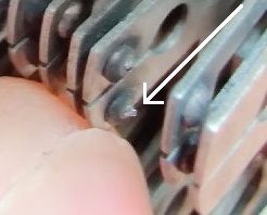
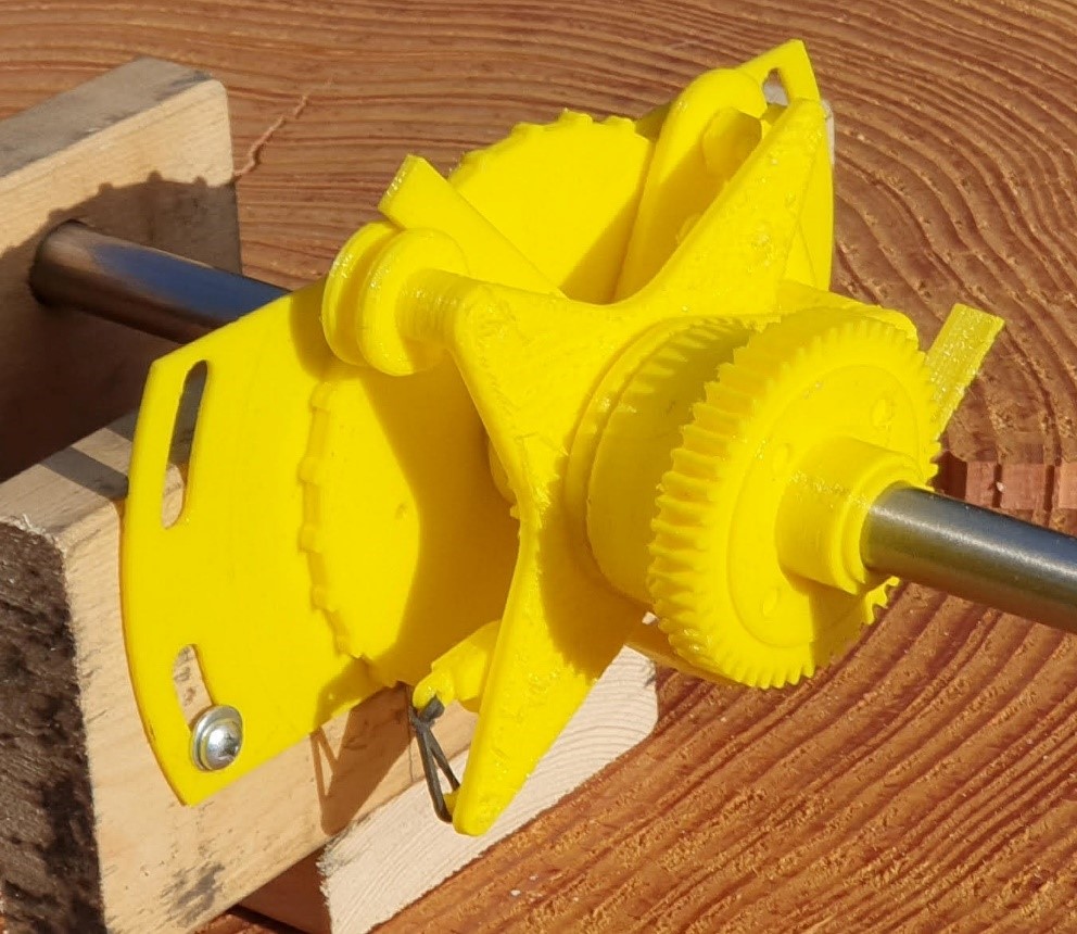
Turing Bombe — John Harper The Drunken Drive Demonstrator Project is now well underway, in three forms. Here is a 3D printed version that is approaching completion –
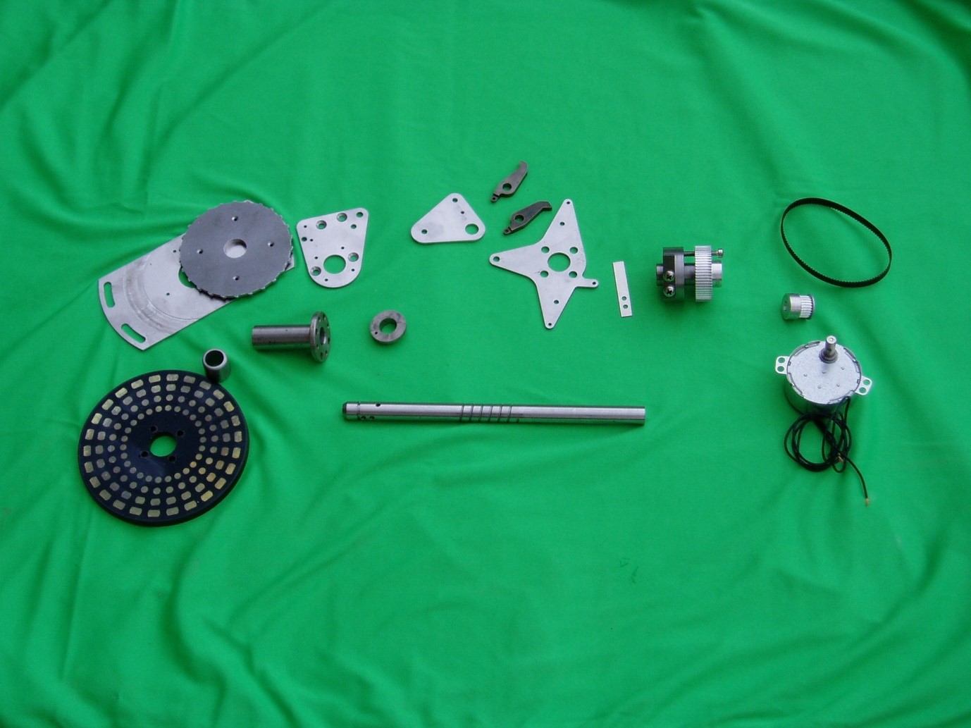
About 90% of the parts are made for the metal version and we are soon to start the assembly stage –
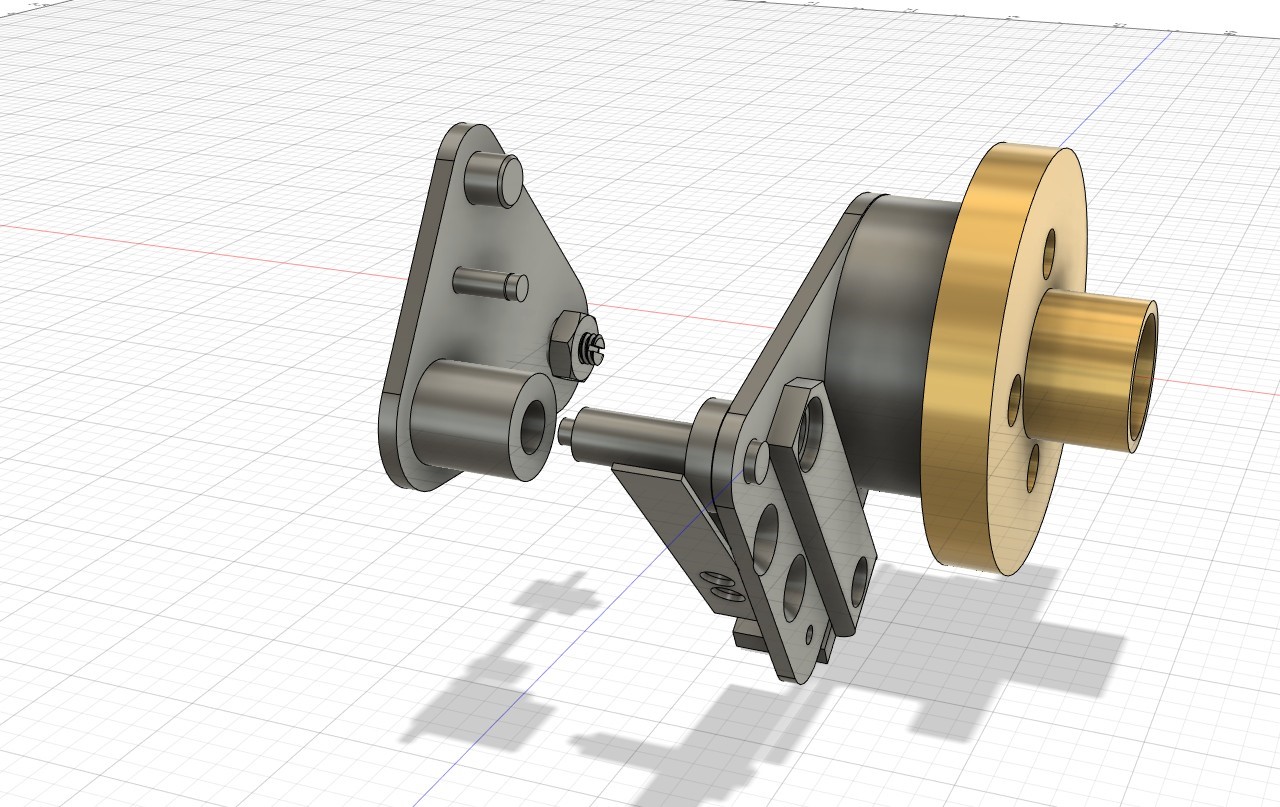
This metal version will be motorised. The third version is an animation that will show the movement in action. This can be show as a video on a screen, as part of a PowerPoint presentation or as a WEB page –
There is another similar project currently being considered to demonstrate the very fast drum shaft arrangement on the four-wheel High-Speed Keen. This movement is not the same as the fast, medium, and slow drum mechanisms on a three wheel machine. |
|
Software — David Holdsworth KDF9 Kidsgrove Algol The Original raison d’être of Kidsgrove Algol was to produce an optimising compiler. Although we are fairly sure that the surviving code that we have was not the final version (nor is it complete), it seems to do quite a good job when not using the optimiser. The production system included an option to omit the optimiser. Perhaps this indicates a lack of confidence in the original system. Bill Findlay and David Huxtable are currently assessing the optimiser using various tests, including Brian Wichmann’s test suite. As a by-product we have evidence that the Findlay floating point emulation is better than mine. Our run-time I/O library includes some newly-written code that has had to be revised as my previous version was using areas of store that were also used by the optimiser. We still have some unresolved issues. Given the uncertain and incomplete status of our starting point, we see our efforts as recreating a likely production system, of which a major fraction is original code. Atlas 1 Dik Leatherdale has been slowly transcribing the Atlas “SERVICE” compiler from a printed source listing from 1972 (when he made the final changes). SERVICE is not really a compiler at all, but a collection of useful utility programs. There is a slight difficulty in that, although the Chilton Computing website has documentation of some of the utilities, many of those which are not intended for general use are absent. If anybody ..... Webserver Issues I have long been aware that the long-term longevity of our on-line preserved systems (Leo III, KDF9, etc) currently depends on the longevity of actual webserver systems. This motivates me to package up the software so that it can be installed on a free-standing machine. My ambition is to release the whole source text under GPL. This motivation coupled with the demise of my desktop Windows-98SE system throws into focus issues of longevity of this software. The C code still compiles and runs. The webserver element of the system uses the Java servlet API, which has undergone some unhelpful (from my perspective) changes. Suffice to say at this point that I have made my own implementation of the Java servlet interface, which is sufficient to run my own webserver, and which functions over a wide range of Java issues. Although it implements a subset of the official javax.servlet API, the source code is all my own. I have not yet completed the packaging of this software, but it is in use. |
News Round-Up
|
Our good friend Herbert Bruderer has been busy again and has published a description on the development of computing power in Switzerland at www.ccsoc.org/bru0.htm. Then he has written descriptions of multiplication and division using Napier’s rods at www.ccsoc.org/bru1.htm and www.ccsoc.org/bru2.htm. 101010101 Ian Elliott responded to the brief article on the 1971 decimalisation problem in Resurrection 93 with some reminiscence of his own ingenious solution. He writes – Centre-File’s shared on-line bureau service for Building Societies went live in July 1969 and anticipated conversion to decimal currency on 15th February 1971. Amounts were stored in units (u) with £1 = 1,200u = 240d = 100p so an old penny was 5u and a new penny 12u. Input was in whole pounds, or £sd with two points like 29.13.6, or like 37.05 in decimal. Output was controlled by a “preferred” format intended to be decimal from D-day but old money could still be displayed. To adjust account balances before D-day, transactions were generated in exact units to follow the regulations. No re-programming or file conversion was required. A full description can be found in DATA PROCESSING March-April 1970 “Decimalisation without tears” by I.R. Elliott (Go to ccsoc.org/notears.pdf for a copy.) 101010101 With this edition we note the passing of Sir Clive Sinclair. In our world Sir Clive was chiefly known for the Sinclair ZX80, ZX81 and ZX Spectrum family of home computers. It is thought that five million Spectra were sold introducing a whole generation to computing in the 1980s many of whom went on to become the backbone of the UK’s IT and games industries. Outside of the arena of computing his interests ranged far and wide from ultra-cheap hi-fi, miniature televisions, the first pocket calculators (which famously sometimes produced the wrong answers) and the Sinclair C5 – a premature attempt to enter the electric car market. Always a controversial figure, his legacy to the world of UK computing is nevertheless, hugely significant. 101010101 |
Queries and Notes
|
An ICT 1900 mystery from Bill Gallagher Back in the late 1970s when at University I asked why all 1900 programs started with an ‘X’. I was given the answer that if you take A=1, B=2 etc and add I+C+L you get X. (I mentioned this when talking to Brian Spoor, who surprisingly had never heard of the I+C+L business.) This also works when adding the 1900 character set values using a 6-bit adder. However, I have recently realised that this explanation is doubtful : –
“If a name is given and if no name has been given in any previously accepted block, the first 4 characters of the name are used as the name for EXECUTIVE. If no name is given in any block, CNSL sets the name to XCOP (unknown compiler object program).” This shows that their use of ‘X’ was to denote ‘unknown’. Can anyone shed any light on this minor ‘known unknown’? |
CCS Website InformationThe Society has its own website, which is located at www.computerconservationsociety.org. It contains news items, details of forthcoming events, and also electronic copies of all past issues of Resurrection, in both HTML and PDF formats, which can be downloaded for printing. At www.computerconservationsociety.org/software/software-index.htm, can be found emulators for historic machines together with associated software and related documents all of which may be downloaded. |
Bronze Plaque to Honour Two Outstanding Historic Computer ProjectsSimon LavingtonOver the last six months four Manchester University alumni have been working to get the IEEE to award ‘Historic Milestone’ bronze plaques for two Manchester computing developments: the Baby computer and its derivatives and the Atlas computer and Virtual Memory.
The IEEE is the world’s largest engineering professional institution, with over 400,000 members world-wide. It has significant resources and a lively interest in the history of technology – for example publishing the Annals for the History of Computing. For the last forty years or so the IEEE has been running its Milestone programme, which honours pioneering achievements which have had long-term effect. So far, about 200 Milestone plaques have been awarded to projects of international significance. After the submission of technical cases running to many pages and long discussions with expert referees, the IEEE-approved text of the two Manchester bronze plaques has just been announced. Each citation has a 70-word limit:
The full proposals can be found respectively ccsoc.org/ieee0.htm and ccsoc.org/ieee1.htm. The lead author for the proposal for the Baby Milestone was Prof. Simon Lavington. The lead author for the Atlas Milestone was Prof. Roland Ibbett. Help with the writing of both proposals was provided by the recently-retired Head of Computer Science at Manchester, Prof. Jim Miles, and by Prof. Roderick Muttram who also acts for the UK and Republic of Ireland Section of the IEEE. An unveiling event is planned in Manchester for both plaques on 21st June 2022 preceded by a special demonstration of the replica “Baby” computer at the Science & Industry Museum and followed by a seminar and reception. CCS members will be made welcome to these events. More details in due course. |
Bryant Discs Re-RevisitedMany MembersJohn Harper’s article in Resurrection 93 provoked much discussion in Resurrection 94 and that, in turn, has stirred members’ memories further. Here we folllow those chains of thought – First from Virgilio Pasquali – The article on Bryant discs brought back many memories. Yes, the Bryant disc was a “pig”, but it was the only high capacity disc available OEM to us (ICT) at the time, and it enhanced the throughput of the system quite significantly (before reliable EDSs of increasingly respectable capacity removed the need for a very large fixed disc.) We used Bryant discs widely. I even remember discussing its attachment to Atlas 2 in 1963 or ’64 with the Bracknell Atlas 2 Supervisor team (but I don’t remember if we ever proceeded with it on Atlas 2). I certainly breathed a sigh of relief when we removed Bryant from our Sales Product List, The idea of those monster discs spinning at high velocity and possibly crashing was not a pleasant thought. Yes, the discs in that period are the subject of many “amusing” stories (though they were not amusing at the time). But we should look at them in the context of those times. From what I remember, IBM had introduced this new storage technology as the main data storage in System 360 and this had opened up a new potentially large market . Many manufacturers were rushing , even without the necessary expertise, into the development of discs. A few disc systems reached the market, even if not perfect (as the recipients, we were grateful for what we got). Other disc developments suffered long delays or were scrapped and never reached OEM delivery. I still wear the scars from one of those. In 1964 we were developing our ICT 1900 Range (an enormous undertaking) and we were planning to announce the Range in September 1964 and to demonstrate two working systems at the Business Efficiency exhibition in London (see www.ict1900.com). Our disc storage was planned to be the Analex 80, an EDS disc system competitive with the IBM 360 offerings. One month before the announcement Analex informed ICT that they were scrapping the development of Analex 80, as they could not make it work. Potentially a major disaster for ICT if we had to cancel the announcement. Peter Ellis (my boss at the time and the head of ICT corporate planning), repositioned the 1900 in the market to announce it with magnetic tapes only. Priced at 5% below the 360, it was projected as a “value for money” system range with “unlimited data store” (magnetic tapes). The new positioning worked and the 1900 took off! Of course, we introduced EDS discs in later years (in 1966, I think, when we introduced the 1901 and relaunched the whole range). Michael Clarke joins in – The disc installed on RRE Malvern’s 1907F behaved perfectly while at West Gorton being commissioned. Then its troubles began as, while en-route to Malvern it suffered an accident, a rather serious accident, the low-loader lorry went into a ditch. The disc suffered some cosmetic damage but had to go back to West Gorton for a thorough check-up. Hence the acceptance trials for the 1907F had to be delayed by about 14 days. Then it almost went through the floor! Only quick thinking and considerable muscle power avoided that ignominy. Then it was the wrong way round and had to be manoeuvred over that weak floor to be the right way round. Another two days lost. So eventually we could begin the acceptance trials which it passed with flying colours. Then it developed a strange noise, the main bearing upon which the disc was mounted had a slightly square ball bearing. It necessitated taking the entire assembly apart to replace it. That took another week. Sadly the machine was never the same and suffered several head crashes. It was replaced by two EDS30 systems later that year after about two month’s use. And he continues – Just a response to the failure rate regarding those large discs on 1900 systems. Pure conjecture, but perhaps relevant and this has to do with the strengthened flooring upon which they stood. Now upon reflection I am beginning to think they were a bit too weak, as when in operation that machine moved rather alarmingly. If one stood next to it the floor was shaking quite a bit – millimetres rather than centimetres but move it did. Now those heads were very close to the disc surface and moving very fast so just the wrong vibration could have been the cause of all those head crashes. Ron Baker reminisces - During my early days as an ICT Field Engineer I spent a short time on a 1500 site which had a Bryant fixed disc. This had to be cleaned regularly with soft-ended paddles, an operation which involved four engineers. The first operated the start and stop buttons to keep the large discs trundling slowly round. Engineer 2 had a paddle soaked in a cleaning solution with which he stroked the slowly-rotating first surface. Engineer 3 replaced him and stroked the same surface with a distilled water paddle. Engineer 4 then repeated this operation with a dry paddle. The trio then did the same on the second and subsequent surfaces until finished. The stroking involved slightly leaning forward to reach into the cabinet and the paddles were brightly colour-coded so as not to be mixed up. The computer rooms had a viewing window so that passing staff and visitors could observe the miracles of modern technology in operation. It was directly opposite the Bryant disc. The cleaning procedure gave rise to much speculation among the staff as to what was going on. The consensus view emerged that this was some sort of pseudo-Buddhist ritual by which the ICT engineers prayed to the Gods of Bryant for a trouble-free following month. It seemed like we were walking round in a circle, each holding a coloured stick and in turn bowing to the open machine. More seriously, a further problem was that the Bryant hydraulic design did not compensate for expansion of these large discs. One of the staff had to come in a couple of hours early to switch on the disc so that it could temperature-stabilise in time for the day’s work to start. If this was not done the outer tracks were unreliable. However I don’t remember the unit vibrating. Perhaps the RCA 301 environment software of the badge-engineered machine was kinder in its use of the drive. Mike Robinson’s brain cells were stirred – If I remember correctly the 1906A was supposed to launch with the Bryant disc and the high speed drum. They never reached the line in time, despite the 6A launch being late. Occasionally Gordon Cooper would approach me to connect the drum to the second prototype 1906A. After an hour or so of head scratching he and his comrades would retreat back to their chairs in the magnetic tape tunnel gathering around the drum to mutter incantations, or so it seemed. Weeks later another request would be received and the sequence repeated. Successful connection of whirring magnetic media came with the EDS 8, the precursor to EDS 30. Nobody warned us about head crashes, so when we experienced the first failure to read from an EDS, we swopped the disc to an adjacent head, ruining two machines in one quick move. Head crashes were fairly common and expensive at first. The other big learning point was when Marketing came to run the Oxford Bench Mark on the second prototype 1906A. They had just run it on a 1904A prototype with a result of about 30 minutes completion. They were leaving the lab for a quick break when the teletypewriter broke into life. I called Pamela Stone-Jenkins back and pointed at the output. She immediately accused us of cheating as the result was correct. After trying again Marketing retreated to confer and consult the disc management team. It turned out that the 6A was just quick enough to do each calculation in the time between segments on the disc. From this observation they went on to optimising disc segment utilisation. Early Days! Some may remember the other big beastie, the magnetic card file. Each card had a substantial frame to hold the magnetic film. The MCF that came to West Gorton was placed inside the entry to Number 3 Shop next to the aisle leading to the car park. Nobody told the MCF designers that punched card readers occasionally mis-fed and spewed cards all over the floor. Soon people were running for their lives in Number 3 Shop chased by spewed MCF cards. The MCF disappeared shortly afterwards. Then John Steele wanders slightly off-topic – I was reminded of a conversation with a man from the RAF in the late 1960s (probably 1968 or 1969) about disc drives. He wanted to put an Argus 400 into one of their research Comet aircraft. As the Argus 400 was designed for process control we could add all of the sensor inputs required. The Argus 400 was also originally designed as a airborne computer. He wanted, quite reasonably, to be able to store a quantity of data and that was the main purpose of our meeting. He had heard we had a disc store available and to him that seemed ideal. This was a Burroughs disc with a head per track (100 tracks) and could store a massive amount of data (for its day) of perhaps 10 Megabyte (from memory). The cabinet was about 4’ high, 5’ long and about 18” wide. He was somewhat taken aback when I asked him a simple question. Do you want the plane to be able to go up and down or left and right? I explained that the disc drive had a single vertically mounted approx. one metre diameter disc of solid metal at least five mm thick. When operating it rotated at 3000rpm and when powered down it could take over an hour to stop spinning. He had not considered the gyroscopic forces that a disc of that size and weight spinning at that speed would create (hence my question which way would the drive face in the plane). We then started discussing magnetic tape options for storage after that. Fortunately Ampex had a rugged version of the IBM-compatible nine-track tape deck that was fully compatible with our magnetic tape controller and he could put this into his Comet without any problem. Finally, [Ed] drives into a ditch – Early ICL 2900s were available with what we (wrongly) called a drum store used for paging. Actually they were fixed head discs and the most popular was the FHD5, a 5MB fixed head disc bought in from Burroughs. They were blisteringly fast but expensive. And we had bought rather too many, the surplus being stored in the Nevada desert to prevent deterioration. But after a few years they started to fail. Somebody contacted Burroughs to ascertain whether they had experienced the same. Well the answer was “no” and matters went no further. My friend Len Cohen was sent in to find out what was going on. When it was all over he explained the problem to me. It seems that Burroughs mounted their discs so that the spindle was horizontal. “But we knew better didn’t we? We ‘knew’ that disc spindles should be vertical. They were always vertical weren’t they? ” So we acted accordingly. Over the course of a few years the bottom bearing end slowly wore away, gradually bringing the disc surfaces rather nearer to the fixed heads than they should have been. Soon head crashes became inevitable. Oh dear. So perhaps those surplus discs turned out to be useful didn’t they? |
Resurrection SubscriptionsThis edition of Resurrection is the first of the 2021-2 subscription period. Subscribers will need to renew their subscriptions to continue to receive Resurrection on paper. Most recipients of the paper edition do not need to subscribe. Go to www.computerconservationsociety.org/resurrection.htm and follow the flowchart if in doubt. And if you do need to subscribe the links so to do are there also. |
The Experimental Packet Switching Service – EPSS
Edward Smith, Jim Norton & Chris Miller
This article aims to provide an engineering-based account of the British Post Office (BPO)’s Experimental Packet Switched Service (EPSS), so that you can understand why it was needed and how the network performed. We’ll briefly look at the origins of the packet switching mechanism and then consider how this came to be adopted by the BPO as a means of addressing the needs of computer users. We’ll then talk about the inception of the project, how this progressed and was overtaken by an international standards-based approach. Then we’ll consider the nature of the Ferranti hardware and the nature of the packet-based protocol devised by the BPO. Finally, the interconnection of customer equipment to the network is described. Conception Packet switching was independently devised by Paul Baran in the USA and Donald Davies in the UK in the 1960s , as a means of efficiently interconnecting groups of computers without recourse to expensive meshes of private circuits. Baran worked for RAND in the US and adapted the store and forward messaging technique used in telegraph and telex systems, where message switching devices (nodes) temporarily stored a message, before passing it onto the next node in the chain connecting users, reducing attenuation in signal strength with transmission distance. His innovation was to segment messages into smaller sections and route these based on the headers added to each section. Smaller units of data would improve the queuing characteristics of the network, making recovery from errors more efficient and permitting faster transmission through use of multiple routes. The goal was to address defence requirements during the cold war, where survivability was vital, needing the nodes to be sited away from centres of population that could be military targets. The routing capabilities inherent in such a network would also provide alternative paths between network end points, reducing the impact of anticipated heavy damage. Davies, a computer scientist at the National Physical Laboratory (NPL), was interested in interactive time sharing systems, which were compromised by inadequate data communications. He knew of message switching in the telegraph system and proposed dividing messages into standard sized packets and having a network of small computers to route packets based on information carried in packet headers. This technique, which he called packet switching, was expected to bring down costs. In December 1965, Davies proposed that the BPO should build a prototype network; but NPL themselves only had resources to build a small prototype network called Mark 1, shown in figure 1. This was built between 1966 and 1969 and operational by 1970. It provided internal services across the NPL site using 768 kbit/s channels and a single packet switch based on a Honeywell DDP-516 minicomputer. Its development was described at a 1968 conference, two years before similar progress in the US was demonstrated.
Davies publicised his ideas, in late 1965 and early 1966 and was made aware of Baran’s work during a UK symposium. In 1967 he learnt of parallel work going on under the US Department of Defense (DoD) funded Advanced Research Project Agency (ARPA) banner. By the end of the 1960s ARPA had funded a variety of time-sharing computers located at universities and other research sites across the US and wanted to interconnect them. This project was known as ARPANET and Larry Roberts, who managed it, learned of Mark 1 at a 1967 symposium in Gatlinburg in the USA. He adopted Davies’ term “packet switching” and some aspects of the NPL design, when considering the development of ARPANET, which was developed and built by consultancy Bolt, Beranek and Newman (BBN); the first 4 nodes being implemented in December 1969. Baran was recruited into ARPA in 1967. It was Davies’ work that would lead to the development of the Experimental Packet Switched Service (EPSS) by the BPO, as described in the next section. The EPSS Project Several BPO engineers attended a 1966 lecture by Davies, resulting in the BPO showing only mild interest. The British equipment manufacturers were much less interested; Baran and Roberts faced similar issues in the USA. Davies maintained good relationships with the BPO, who took an independent approach but were lukewarm at senior levels. The Real Time Club, driven by founder member Stanley Gill of Imperial College, exerted pressure on the BPO to improve its provision for data communications and in November 1969 submitted a proposal to the Postmaster General for an experimental network. At this time, the BPO was managing the transition from being a Civil Service department to a nationalised industry. Data, although an increasing part of its business, was dwarfed by the growing and investment-hungry voice business, whose switching infrastructure was in need of expensive modernisation. The transition to a public corporation gave BPO staff more freedom to innovate, allowing them to work closely with NPL and others, whilst maintaining an independent approach. Scantlebury, one of Davies’ team at NPL, was seconded to the BPO in 1969, participating in a data communications study. He worked closely with M. A. Smith supervising four data communications-related research contracts. These fed into a study of an 18-node hypothetical model network in 1970-71, which recommended a network capable of operating in circuit-and packet switched modes. Gardner of the BPO was seconded to NPL, working on the development of a Mark II network. Like most communications providers and in-line with the thinking of CCITT (Comité Consultatif International Téléphonique et Télégraphique – the international body responsible for telecommunications standards), the BPO favoured circuit switched data networks rather than packet switching but hedged their bets on both technologies. Their 1974 tender for a circuit switched network yielded responses that were not economically viable and development was delayed pending changes, known as System-X, to the switched telephone network. This gave more impetus to consideration of packet switching. By 1970 the BPO-T started to specify a packet switched network and in August 1973 an experimental packet network, known as EPSS, was approved. The UK was the first country to announce a public packet network. M.A. Smith’s team of BPO engineers designed a packet-switching protocol for EPSS from basic principles. The contract for development of the hardware and software for the service was placed with Ferranti in August 1973; the £750,000 deal covered 13 Argus 700E computers, each with 48 Kbytes of memory, to be housed in three sites. The use of a commercial processor was expected to allow an initial experimental capability to be available by the autumn of 1975, reducing the development work required. The trial formally started in April 1977, using three Packet Switching Exchanges (PSEs) located in Glasgow, Manchester and London, with each PSE consisting of several fully-interconnected Packet-Switching Units (PSUs) and a Monitor and Control Point (MCP) for network control. The PSUs and MCPs were based on the Argus 700E, but the packet line cards for the customer interface were a bespoke development. Users were not billed for data usage, but tariffs were devised and dummy bills issued, the BPO reserving the right to charge in line with such tariffs. Prospective charges were higher than expected, potentially deterring customers from joining the service. Early experience was obtained in 1974 from collaboration between NPL and the Computer Aided Design Centre, Cambridge, using EPSS protocols and a direct connection; there were 40 trial participants on the experimental network by 1st March 1976. As is typical of new and novel projects, Ferranti struggled to deliver the hardware and software for EPSS. The service initially had restricted hours with limited functionality and resilience, but scope and performance increased as Ferranti’s software improved. For the initial release the average PSU failure rate was one fault every 90 minutes. By 25th April 1977, the network was sufficiently stable to allow customers full access; with Ferranti delivering the final software in 1978, enabling the release of test hardware, which was used to allow dual-processor hot-standby operation and greater resilience at the London PSE. There were four phases of implementation:
In 1974, representatives from Britain, France, Canada, and the USA met to discuss the standardisation of packet-switched networks, leading to the CCITT, in October 1976, agreeing Recommendation X.25 as the definition for a packet switching protocol. The experience with EPSS put the BPO in a strong position to influence the direction of this emerging international standard. A 1976 government inquiry, examining data networks and emphasising national economic and social factors, confirmed the importance of such a network. After two years deliberating, it recommended the development of a national packet switched network, to be provided by the BPO and compatible with international standards. BPO met this challenge, but were mandated to consider only tenders from British firms. Four tenders were considered, revealed by industry sources to be Plessey, Ferranti and two British software houses Logica and Leasco. Plessey, using equipment sourced from the US company Telenet, were the favourites, since the licensing agreement between the two companies allowed Plessey to incorporate Telenet hardware/software in its own solutions. Furthermore, Telenet were an offshoot of BBN and headed up by Larry Roberts and therefore had a strong track record in an emerging field. In addition, this was already being used by the BPO for the London node of an international link to the USA. Having considered the project and its delivery, we now move onto consider the hardware foundations upon which the service was built. The Ferranti hardware and software
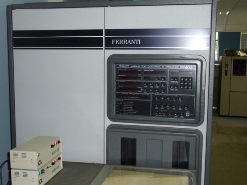
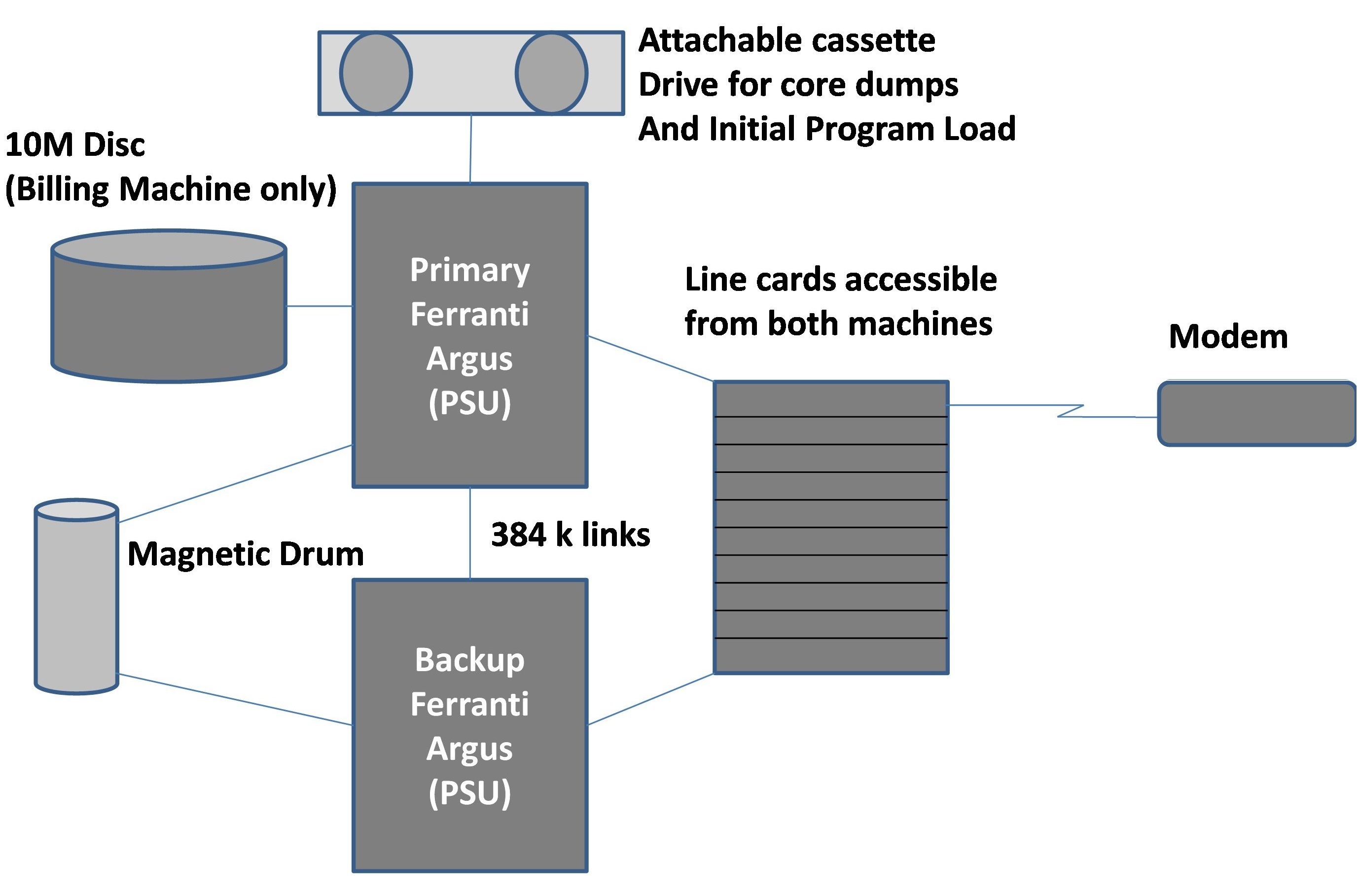
The Argus 700E used a 16 bit word and could address 64K words of memory and up to six I/O processors or channels. Each PSU comprised two processor shelves, each comprising a CPU board, four memory boards each housing 16k words of ferrite core memory and channel cards. They were initially provided with 48K of core store (later expanded to 64K), two fast multiplexor (TFX) channels, and a processor interconnection channel (PIC). Resilience could be achieved by deploying processors in live and standby pairs. The standby processor was continuously updated with system statistics and packet information, but was isolated from the line equipment by the on-line processor which, on failure, allowed it to takeover packet processing.
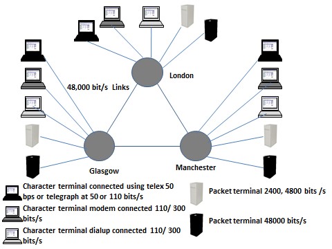
Three PSUs were installed in the London PSE, each with duplicated processors, for high availability. Two single processor PSU configurations were provided at Manchester and one in Glasgow, allowing the reliability and operational aspects of duplicated and non-duplicated systems to be compared. A fourth node at a second London site was used for billing and had a 10 Mbyte exchangeable hard disc drive, connecting to EPSS via a 2,400 bit/s packet link. The three PSEs were connected by 48 kbit/s trunks (three from London to Manchester, two from Manchester to Glasgow and one from London to Glasgow). Packet mode customer connections were provided at 2400, 4800 and 48000 bit/s and character mode, typically at 110 or 300 bit/s. The connections available on the opening dates were as shown below:
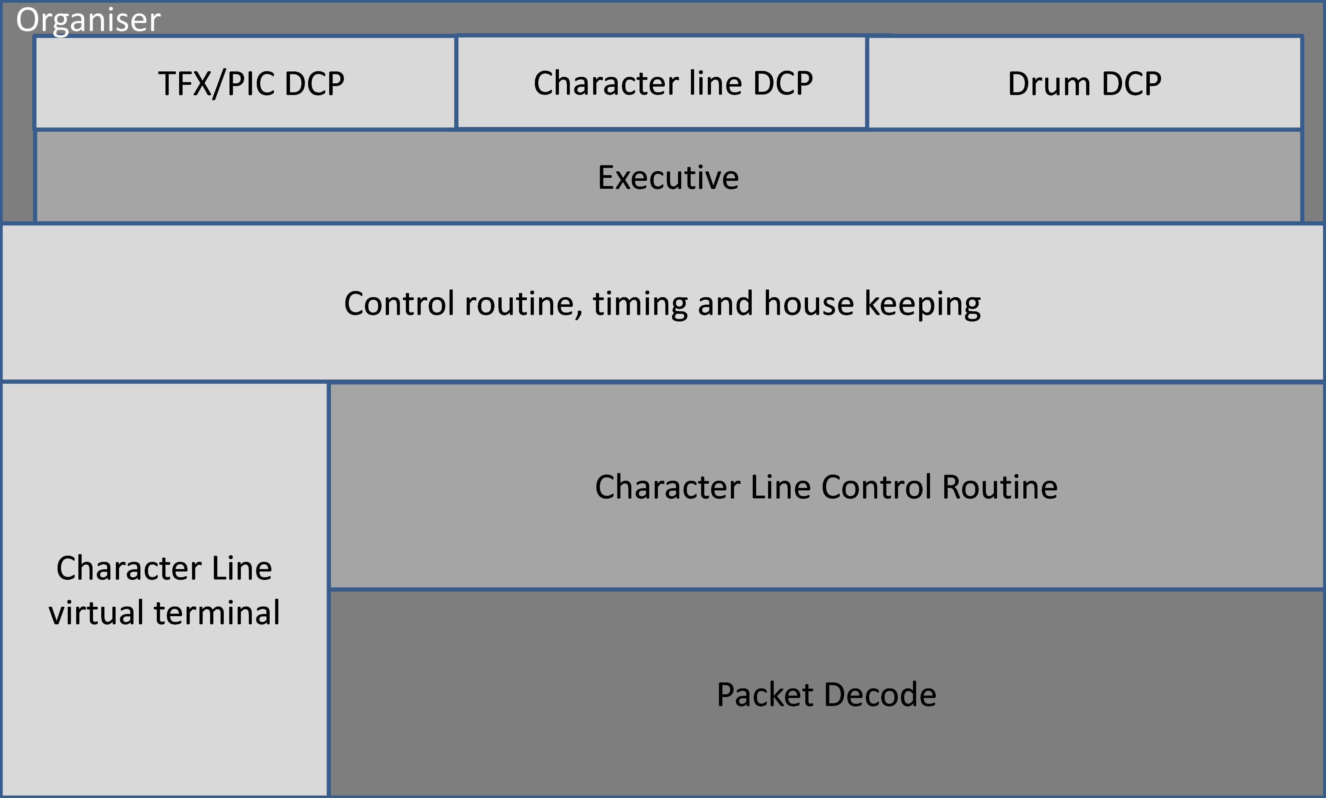
Character terminals used a program driven asynchronous character handling interface card capable of supporting speeds of 50 to 4,800 bit/s. All character line connection equipment was common and controlled by the current on-line processor. Packet and character lines were connected to the machine using line interface cards forming a block of common interface equipment, which could be addressed by the currently on-line PSU. The line exchange capacity was shared between the PSUs, each of which addressed about a third of the available PSE line cards. Failure of one module did not result in the total loss of a service. The packet line cards (PLC) were specifically developed for EPSS and supported circuits working full duplex synchronously at 2.4k, 4.8k, 9.6k or 48 kbit/s for customer packet terminal interfaces and inter-PSE trunks. The same logic was used for both purposes, but wired differently according to use. The PLCs interfaced to the processor using the TFX which was a microprogrammed module that scanned a small number of fast I/O devices and passed data between them and processor core store without processor intervention. The links between PSUs in the same PSE or to the MCPs used a PIC to provide a memory to memory connection. The PIC was similar to the TFX and could multiplex up to eight full duplex lines at an aggregate throughput rate of 800 kbit/s, enabling processors to interconnect at 384 kbit/s. The MCP was based on a Ferranti Argus 700E with 24Kbyte of memory and had a slow printer, a visual display unit and a four deck cassette tape system. The EPSS software was built on the Argus 700 operating system, which provided executive functions and Device Control Programs. The executive provided overall program control, interrupt handling, scheduling, memory allocation and the means of program interaction. The Device Control Programs (DCP) controlled access to peripherals. Its basic form is shown in figure 6.
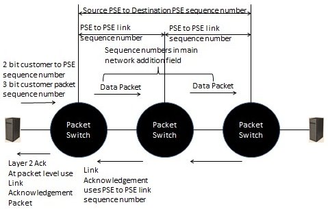
Information flowed between software modules using EPSS formatted packets and call protocols, allowing some single PSU, single drum configurations to be supported by redirecting information to a slave drum at an alternative site via the network. Inter-processor communication did not use EPSS packet formats or call protocols. If a control computer failed, the standby computer took full control within 100 milliseconds of detecting the failure. Packets in transmission when the changeover occurred were lost and had to be retransmitted. Programs were entered on a line by line basis at a terminal and editing was done using a command-line based text editor. Once a program was compiled, it was punched out to paper or Mylar tape, which was the most reliable means of storage. This could then be read back in to the computer. Due to the operating system not implementing the code and data separation capabilities inherent in the hardware, machine crashes were not uncommon and under such circumstances the core image had to be transferred to cassette tape for analysis by specialist BPO staff. The EPSS Protocols The BPO developed the EPSS protocols themselves and literature evidence shows minimal reference to work done elsewhere, which given the influence of Davies and NPL is surprising. The design was based on a 256 byte packet, comprising header, data and error-check-bit fields. Whilst employing many principles later adopted by the X.25 standard, EPSS was very different at the detailed level. X.25 and EPSS both used the concept of virtual calls, with calls initiated by the source terminal and established if the destination and network verified that the call was legitimate and sufficient resources were available to support it. Following call establishment, the call was allocated a unique source label allowing the PSE to distinguish between simultaneous calls from a customer and allowing the called address to be omitted from subsequent packets on the customer to PSE link. Only one packet could be transmitted on the link from the PSE to the receiving terminal before an acknowledgement was received, ensuring correct ordering of packets. The link protocol came in two forms; the standard and simplified form. The former optimised throughput, by returning a response to a packet received as quickly as possible by briefly interrupting any packet being transmitted. The delay characteristics of the link had to be monitored and measured, in order to achieve this. Once a packet was acknowledged the PSE checked the customer to PSE link sequence number, discarding any out-of-sequence packets. The packet transmission procedures for inter-PSE traffic used a similar process to the simplified process, with the final exchange before delivery to the customer maintaining packet order. The inter-PSE packet transfer procedures are summarised in the diagram below:
For asynchronous character-mode terminals, the packet assembly and disassembly facility was performed by virtual packet terminal (VPT) software in each PSE. This could form all the packet types necessary for normal transmission on behalf of the asynchronous terminals. Interfacing Computers to EPSS
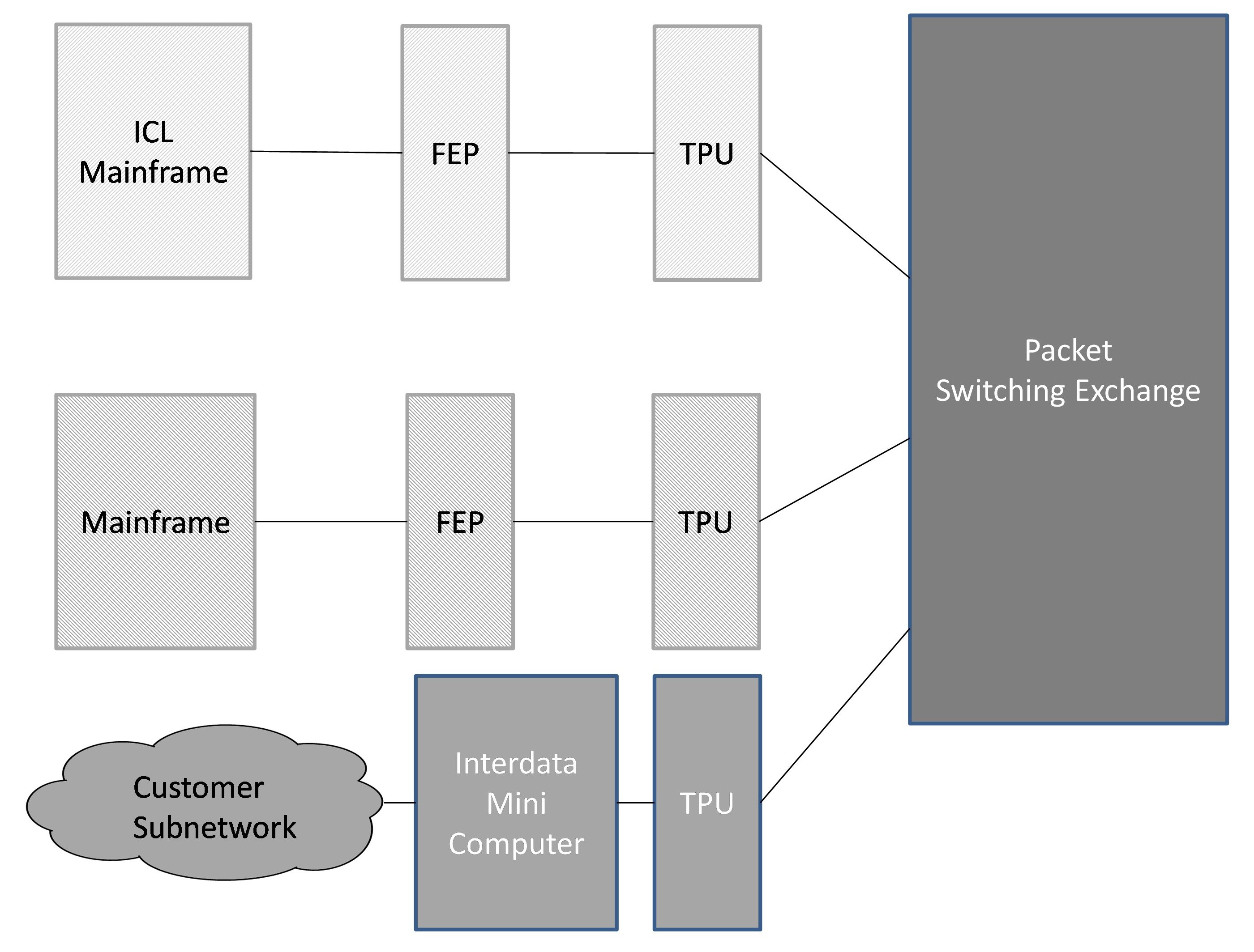
Having described the network it is important to understand how customer equipment interfaced to it. Study groups, comprising BPO personnel, customers and the computer industry specified a bridging protocol (designated level 4) which provided control over the functions of the packet layer (arguably a precursor of OSI level 4) and a set of high level protocols that covered specific applications such as file transfer, job transfer and character terminals. These protocols needed to be implemented on the customer’s equipment. Three approaches were taken, with many computer manufacturers seeking to minimise the impact on their existing mainframe and front end processor (FEP) hardware and software. These are shown in figure 8 and are:
Conclusion This paper has examined the development of the UK’s first commercial packet switched service, which was a very early ancestor in the evolutionary path leading to today’s information rich connected world. It has covered: the origins of the packet switching mechanism, its adoption by the BPO, the inception of the project, the emergence of an international standards-based approach, the implementation using Ferranti hardware, the packet-based protocol devised by the BPO and the interconnection of customer equipment. We have demonstrated why the network was needed and how the network performed. Despite the limitations of the equipment available and the time taken for administrations (the BPO in particular) to become interested in the technique, EPSS made a major contribution to establishing packet switching as a viable capability. EPSS was a two year, fixed capacity trial, but generated a great deal of attention during its short life. The project had attracted attention from 31 organisations by June 1974, rising to 38 organisations by January 1975 and fluctuating between 34 and 43 during the life of the trial. Trialists were largely draw from universities, research establishments and a smaller number of commercial organisations. By the autumn of 1977 more than 75% of customer terminals had been connected successfully and 42 out of the total 47 packet ports were in use. The network was handling about 140,000 packets per day, but much of these arose from network trial activity and overall levels user traffic levels were lower than anticipated. This work was carried out in an era when the PTOs operated a “permission to connect” policy, resulting in a considerable amount of effort from the BPO helping customers verify their protocol implementations. However collaboration was two-way with customers contributing strongly to the joint study groups which established the higher level protocols. This generated the expertise within both camps to take full advantage of the successor X.25 protocol, when it became available. |
Contact details
Readers wishing to contact the Editor may do so by email to
Members who move house or change email address should go to
Queries about all other CCS matters should be addressed to the Secretary, Rachel Burnett atrb@burnett.uk.net, or by post to 80 Broom Park, Teddington, TW11 9RR. |
Programming CSIRAC
Bill Purvis
CSIRAC was the first Australian digital computer. It was designed by Trevor Pearcey, an Englishman who emigrated to Australia in 1945 to work for CSIRO, the Commonwealth Scientific and Industrial Research Organisation, hence the name – although initially it was called the CSIRO Mark I. The name was changed to CSIRAC when it was decommissioned and handed over to the University of Melbourne in 1956 where it provided a computing service until 1964. Architecture The machine was designed around the use of mercury delay lines for the main store. Unlike other machines of that period, the word length was quite short, only 20 bits, but this was considered to be adequate for the kind of calculations originally intended. Higher precision could be achieved in software by use of double-length subroutines. The machine was designed with the goal of having 1024 words of memory, stored in mercury delay lines. Initially each line contained 16 words, but after the machine was working they found they could interleave the data in each line, so achieving 32 words per line. With the goal of 1024 words they constructed a total of 32 lines, but sadly, they found that there were always several of the lines out of action. In practice, they fell back to running with 24 lines, giving a total of 768 words. Additional store was provided by a magnetic drum store. This had four tracks, each equivalent to the maximum main store of 1024 words. Each word was individually addressable, and could be thought of as an simple extension of store. The only problem was each track was accessed via a different source or destination function code. Unlike the other machines of that vintage, it was not based on the use of a single accumulator. It had instruction sets consisting of a function code and an operand, and a number of registers which could be accessed. Each instruction consisted of two function codes, one of which derived a 20-bit value, known as the SOURCE, and a second code which performed actions on that value. In some ways it can be thought of as a two-address machine, but as it only had a single address operand, it did not qualify as a true member of that class. I find that there are some aspects of the machine that suggest microprogramming – a concept initially proposed by Wilkes some time after CSIRAC was operational, but again it fails to qualify for that honour. As the two function codes were each five bits, it could therefore be thought of as a single function code of 10 bits, which implies a total of 1024 different instructions, way beyond the range of other machines. In practice many of the combinations are of little practical value, and I find it better to think of it in the original terms, two operations, one deriving a value, the other operating on the derived value and/or specifying the destination of the result. Registers As already stated, CSIRAC had a number of registers which could be used for arithmetic or logical operations. These were named A, B, C and D, but D was actually 16 registers, so in total there were 19 registers. Any of these could be used as a source or a destination, and in addition, the arithmetic unit could perform the basic operations of addition and subtraction on the destination. For example the instruction: B PA would take the value in the B register and add it to the content of the A register, leaving the result in A. Multiplication was a bit more complex, and required specific registers. The XB destination would place the source value in the B register, then multiply that by the C register, adding the double-length result into the combined A and B registers. A simple multiplication would need the A register to be cleared beforehand, and this was often done using the CA source function. This would load the content of the A register as the source, then clear the register. Thus the sequence: CA XB often appears in programs, though the combination of addition into A with the multiplication was also useful, for coding such as inner products. The current program address was held in the S register, which was incremented as each instruction was decoded, and could also be modified by the program. As this value is going to be used to address the store, the significant part is bits 11 to 20. The lower order bits are effectively ignored unless used for devious purposes. A short register, H, which only held 10 bits was used to transfer half words between upper and lower halves of the registers. Additional registers included an input register, which held the data from the tape reader, an output register which fed the tape punch, and two switch registers which allowed the operator to provide additional control inputs. It is also possible to use the operand as a value. While it is not a general register, the instruction register (K) is accessible as a source using the K source function, and the PK destination function provides a means of modifying the operand part of the following instruction. Normally, the K register is cleared during execution of an instruction, but this takes place after the source function is performed, and before the destination function. When the following instruction is read from store, it is added into the K register, so the effect is to modify the address part. This allows array accesses to be indexed without needing to modify the instruction in store. Programming When writing code, the programmer would normally specify an operand address and the two function codes. Coding was written in a strict format, using special coding forms. Two columns were reserved for special modifiers, then two groups of two-digit numbers in the range 0 to 31, separated by a space, then a further two groups of two-character mnemonics, again separated by single spaces. This would be transcribed by the punch operator as two rows on 12-hole tape using a specially developed keyboard and punch. The keyboard had 32 keys which were numbered 0 to 31, and also marked with mnemonics, thus providing a simple means of encoding the orders. In addition the keyboard had additional keys, labelled X and Y, and a further blank key. The latter key caused the row to be punched. Addresses were always written in base-32 format, that is two numbers in the range 0 to 31, with the ‘normal’ value being 32 times the first, plus the second. If either of these numbers were 0 they could be omitted, relying on the fixed format of the form to distinguish between the cases. Thus, 167 would be written as ‘ 5 7’, while 160 would be written as ‘ 5 ’, and 7 as ‘ 7’. The address part was always typed first, followed by the blank key, then the mnemonics, followed by ‘ X’, and then the blank key. If the address was all zeros, or irrelevant, then that row was omitted, and just the row with the order mnemonics was punched. The program loader provided similar facilities to those implemented on the Cambridge EDSAC, so that library routines could be simply copied onto the tape, and linkages between them would be resolved at load time. The loader simply responded to the two control bits on each row. These were referred to as X and Y. If neither bit was punched, the 10 data bits would be set aside as the operand address or value. If the X bit was punched, then the row was taken to be the function codes, any previous operand would be added in, and the resulting word stored at the current load address. If, on the other hand, the Y bit was punched, this was taken to be a control function. The loader maintained a list of routine addresses, either in low store, immediately following the loader itself, or it could be held in the D registers. Variants of the loader for either case were available and were punched at the head of the program tape. The functions available to the loader were:
The control sequences to achieve these functions were punched by the punch operator, when instructed by shorthand notations in the program code. The convention was that each subroutine had a unique number, other than 1, but each was also referred to as 1 as it was loaded. Orders with an address which would need to be relocated were prefixed by a modifier written in the first two columns of the coding sheet, which were otherwise left blank. The actual coding of these functions was supplied by the punch operator, and consisted of a couple of rows, with the Y punch in place of the X punch. In general, a program would be constructed as a sequence of subroutines, followed by a main routine, and finishing with the control sequence to execute the first instruction in the main routine, which was usually a halt order. The operator would then ensure that any data tape, usually on five-hole paper tape, would be loaded, and control switches specified would be set, then the machine restarted to execute the main routine. The punch operator would copy the loader from a library tape as the first section of the program tape, punch the appropriate function codes to set the load address to a suitable value, then take each of the library routines, punch a suitable function sequence, the copy the library tape, repeating this until all of the library tapes were included, then punch the main routine, including functions to add the subroutine address where appropriate. Input and Output As already stated the CSIRAC was unusual in having 12-hole paper tape facilities. In some ways this resembles punched cards, and the use of X and Y probably derives from punched card notation. I had never encountered 12-hole tape until I started looking at CSIRAC. In addition there were also the usual five-hole punch tape facilities, with Friden Flexowriters used for preparation and printing of data and results. The machine had two selector switches, one for input and one for output, and the position of the switches determined whether the operation was for five-hole or 12-hole tape. There was also a Creed teleprinter on the console, which was reserved for output of operator messages, or very short results. The tape punch was much faster than the printer, so any substantial results would be output to the punch for printing offline. One minor difficulty was that the printer and punch character sets were different, so if you needed to switch between them you had to have some kind of lookup table to map characters to the device. In most cases, a program was written with a specific device in mind and the output coded accordingly. Example Here is a segment of code as an example. The table below briefly describes the source functions and destination/operation functions used in this example.
Note * means that the least significant four bits of the address field are used to specify which of the 16 D registers is to be accessed. A simple loop, summing squares of 10 words of data from store(512...):
You can see that programming this machine was an interesting problem, and involved making many choices of how to implement any given algorithm. Further details I have set up some web pages which go into a bit more detail of the machine, with tables to list the various function codes, character sets, and further descriptive details about the machine. Also included are details of how to download and run my CSIRAC Emulator. Go to: www.billp.org/CSIRAC. 1. There are other ways to set a register to zero, but the above use of subtracting the register from itself seems to have been a favoured method. I recall the same trick used in IBM 360/370 assembler as being the shortest method (two bytes), but for CSIRAC there is no real advantage that I can see. 2. Note that 9 is both the index to the D registers and the value set. As the count has to go negative to terminate the loop, the value needs to be n-1. To set a D register to a value other than its index would require an additional instruction and a free register. 3. There is no function to subtract from S, so we have to add -7 (31,25) to S instead. 4. S is incremented at the start of each instruction and so contains the address of the next instruction. |
||||||||||||||||||||||||||||||||||||||||||||||||||||||||||||||||||||||||||||||||||||||||||||||||||||||||
50 Years ago .... From the Pages of Computer WeeklyBrian AldousMore nations back GEC’s ‘watchkeeper’: The computer-based automatic watchkeeping system developed for the marine industry by GEC-Elliott Process Automation which was earlier this year granted type approval by Lloyds Register has now received similar approval from the American Bureau of Shipping and the French Bureau Veritas. Another GEC company, Marconi Space and Defence Systems, has also developed a sea-going system for ships – a radar processing system which displays the position of ships detected from radar inputs on a CRT screen, and also estimates the outcome of avoidance courses recommended by the computer in congested shipping lanes. The anti-collision system has been installed for sea trials in the Methane Progress, a tanker managed by Shell Tankers on behalf of British Methane, a jointly-owned subsidiary of the Gas Council and Conch International Methane. The ship plies between Britain and Algeria – a route which includes two of the most confined waterways in the world, the Straits of Gibraltar and the English Channel. (CW 9/9/1971 p3) 1900/Micro 16 coupler developed by Digico: With the full knowledge and approval of ICL, Digico Ltd has developed a processor coupler for 1900 series computers to link Micro 16 or Micro 16-P computers as front-end processors. The first unit of the new hardware has been installed with a Micro 16-P at East Anglia University, Norwich, and two more orders, also for universities in the UK, are in the pipeline. At Norwich the Digico hardware replaces an ICL multiplexer and when the software is complete will be used to drive 10 Teletype terminals. The maximum number of terminals it can take is 16. Digico’s joint managing director, Keith Trickett, says that while 1900s are the only computers so far for which they have made a processor coupler, they have their sights on other computers, possibly System 4 and IBM 370, although he would give no indication of the timescale on this. One of the benefits of the coupler is its speed. It is very much faster than the British Standard Interface, and Mr Trickett claims that, in fact, data speeds are only limited by the speed of the 1900 central processor. The coupler has been designed to look like the inter-processor buffer of ICL’s 7901 front-end processor, so that standard software packages can be used, and the only change necessary to the operating software is the addition of a 7901 Executive patch. (CW 16/9/1971 p1) Post code trainer accepted: The mechanisation division of the Post Office has now completed acceptance trials of the Honeywell 516 system installed at its Croydon sorting office to assist in the training of postal sorters. To simulate the letter coding desks at which sorters will translate the post codes of letters into the phosphor dots which are recognisable by automatic sorting equipment, the 516 system has eight trainee positions, each consisting of a keyboard and VDU. During a 100-hour course spread over several weeks sorters will spend at least 60 hours at the training keyboards. On successive phases of the course the sorters will be led from the stage of learning to touch-type, by keying in the character which is flashing on a VDU display of a complete keyboard, to the final one in which the training position fully simulates a letter coding desk. To monitor the trainee positions, the 516 system has a supervisor desk with a VDU, a keyboard, and an audible alarm. It permits two-way transmission between supervisor and trainee screens so that mistakes can be pointed out and advice given directly. The system informs the supervisor if the trainee exceeds a predetermined error rate during a session, and it provides performance data on individuals and the class as a whole at the end of a session. The 516 system, for which special software was written by Honeywell, includes 16K of memory, a one megaword disc file, and a display controller. It can be expanded to 20 trainee positions. (CW 23/9/1971 p1) Programma 602 Launched by Olivetti: For an increase of a third in the price and offering six times the power of the Programma 101, Olivetti is launching the Programma 602 microcomputer in the UK at the Business Efficiency Exhibition, following its United States debut three months ago. The P602 has a basic desktop unit which is similar in size to the P101, and its price is £1,985 as compared with £1,485. But the P602 also has its own peripherals – a 28K random access memory on a magnetic tape cartridge, paper tape reader and paper tape punch. It can also work with a graph plotter or be linked on-line to scientific instruments. Olivetti has provided a good deal of software back-up for the P602, with a program library, a team developing special purpose packages and six customer support centres in different parts of the UK. Programs can be preserved on magnetic cards similar to those used for the P101. The price of the full P602 configuration including magnetic tape cassette, paper tape reader and paper tape punch is £3,985. CW 30/9/1971 p1) PDP-11/45 giant mini launched by Digital: By incorporating recent advances in high-speed logic in the architecture of the PDP-11 range, Digital Equipment has produced the PDP-11/45 which is claimed to be up to seven times faster than any other processor in this range, but to be only about twice the price of the PDP-11/20, previously the most powerful. The new PDP-11/45, which can have up to 124K of 16-bit word memory, is described as a giant minicomputer to bridge the gap between minicomputers and medium-scale machines. Typical prices will range from £9,500 to £100,000, and it is intended primarily for scientific computing, simulation, and OEM use in general. Deliveries will begin in mid-1972. The first UK order has been received from Instem Ltd, of Stone, Staffordshire, which specialises in on-line real time process control and data acquisition systems. The company will use its PDP-11/45 for software development for its gas chromatography, mass spectrometry, and nuclear magnetic resonance laboratory systems. (CW 14/10/1971 p1) Council to go on-line with VDUs: On-line data preparation through 10 visual display units will be one of the features of Staffordshire County Council’s computing when its IBM 360/30 is upgraded next July by the installation of a 370/145 central processor. The plan to continue with IBM computers is said to be definite, in spite of protests by local MPs and others that the county where ICL has a manufacturing plant (Kidsgrove) should be persuaded to use a British computer. The county council has had its Model 30 installed since 1967. (CW 4/11/1971 p1) VAT work to be run on 4/72: Faced with a lot more accounting when Value Added Tax, VAT, is brought into effect in April, 1973, HM Customs and Excise, which will administer the tax, has ordered by single tender from ICL, a System 4/72 estimated to be worth about £700,000. The 4/72 is due to be delivered to the Customs and Excise DP centre at Southend in the first half of next year, and is expected to have been fully commissioned by the middle of the year. Prior to the delivery of the 4/72, Customs and Excise staff will develop the programs for it on a System 4/50 which has been transferred to Southend from the Department of the Environment centre at Swansea where it has been used on the vehicle licensing project. When it has served this purpose the 4/50 will be used for the payroll, statistical and other departmental work which is currently done on an ICL Leo 3 at Southend. The latter machine will be gradually phased out. The 4/72 consists of a 320K byte CPU, two EDS 30 three-spindle disc units, 20 magnetic tape decks, two card readers, three line printers, and one paper tape reader. The preponderance of magnetic tape decks would seem to indicate that Customs and Excise has opted for what will basically be a simple batch system, and that it is playing safe in a current situation in which a lack of vital information about VAT is making life unnecessarily difficult for the designers of equipment and programs. (CW 18/11/1971 p1) |
Forthcoming EventsFace-to-face meetings at the BCS in London have now been resumed. It is as yet uncertain when Manchester meetings will recommence. However, in view of the success of the online Zoom meetings that have taken place over the last year in allowing many more members to attend, we are now operating in hybrid mode by making meetings available over Zoom as well as in person. Seminar Programme
London meetings take place at the BCS — 25 Copthall Avenue Moorgate EC2R 7BP starting at 14:30. The venue is near the corner of Copthall Avenue and London Wall, a three minute walk from Moorgate Station and five from Bank. You are strongly advised to use the BCS event booking service to reserve an in-person place at CCS London seminars in case the meeting is fully subscribed. Web links can be found at www.computerconservationsociety.org/lecture.htm . The service should also be used for remote attendance. For queries about meetings please contact Roger Johnson at r.johnson@bcs.org.uk. Details are subject to change. Members wishing to attend any meeting are advised to check the events page on the Society website. MuseumsDo check for Covid-related restrictions on the individual museum websites.
SIM : Demonstrations of the replica Small-Scale Experimental Machine at the Science and Industry Museum in Manchester are run every Wednesday, Thursday and Friday between 10:30 and 13:30. Admission is free. See www.scienceandindustrymuseum.org.uk for more details. Bletchley Park : daily. Exhibition of wartime code-breaking equipment and procedures, plus tours of the wartime buildings. Go to www.bletchleypark.org.uk to check details of times, admission charges and special events. The National Museum of Computing Normally open Tue-Sun 10:30-17.00 but at present opening days are somewhat irregular so see www.tnmoc.org/days-open for current position Situated on the Bletchley Park campus, TNMoC covers the development of computing from the “rebuilt” Turing Bombe and Colossus codebreaking machines via the Harwell Decatron (the world’s oldest working computer) to the present day. From ICL mainframes to hand-held computers. Please note that TNMoC is independent of Bletchley Park Trust and there is a separate admission charge. Visitors do not need to visit Bletchley Park Trust to visit TNMoC. See www.tnmoc.org for more details. Science Museum : There is an excellent display of computing and mathematics machines on the second floor. The Information Age gallery explores “Six Networks which Changed the World” and includes a CDC 6600 computer and its Russian equivalent, the BESM-6 as well as Pilot ACE, arguably the world’s third oldest surviving computer. The Mathematics Gallery has the Elliott 401 and the Julius Totalisator, both of which were the subjects of CCS projects in years past, and much else besides. Other galleries include displays of ICT card-sorters and Cray supercomputers. Admission is free. See www.sciencemuseum.org.uk for more details. Other Museums : At www.computerconservationsociety.org/museums.htm can be found brief descriptions of various UK computing museums which may be of interest to members. |
North West Group contact details
|
||||||||||||
Committee of the Society
|
Computer Conservation SocietyAims and ObjectivesThe Computer Conservation Society (CCS) is a co-operative venture between BCS, The Chartered Institute for IT; the Science Museum of London; and the Museum of Science and Industry (MSI) in Manchester. The CCS was constituted in September 1989 as a Specialist Group of the British Computer Society (BCS). It thus is covered by the Royal Charter and charitable status of BCS. The objects of the Computer Conservation Society (“Society”) are:
Membership is open to anyone interested in computer conservation and the history of computing. The CCS is funded and supported by a grant from BCS and donations. Some charges may be made for publications and attendance at seminars and conferences. There are a number of active Projects on specific computer restorations and early computer technologies and software. Younger people are especially encouraged to take part in order to achieve skills transfer. The CCS also enjoys a close relationship with the National Museum of Computing.
|
