| Resurrection Home | Previous issue | Next issue | View Original Cover | PDF Version |
Computer
RESURRECTION
The Journal of the Computer Conservation Society
ISSN 0958-7403
|
Number 72 |
Winter 2015/16 |
Contents
Society Activity
|
Harwell Dekatron/WITCH — Delwyn Holroyd et al. The machine continues to run daily for the benefit of museum visitors and visiting schools. Thanks to a mispositioned switch, some of our demonstrators have been surprised by the hitherto unknown (to them) auto power down feature. This very early example of green computing causes the machine to turn itself off after a period of inactivity! No significant maintenance has been needed apart from the usual one or two store anode resistors and clamping diodes which continue to expire. |
|
HEC1 — Kevin Murrell The HEC 1 computer has now been transferred from the storage centre in Birmingham to The National Museum of Computing. The machine is on an inter-museum loan for three years. It is expected by both parties that this will be regularly renewed. The computer has been in a disassembled state since 1972 when it was donated to Birmingham by ICL. We are trying to determine the route the machine took since being built by BTM in Letchworth. We have a smart new display case for the computer ready and waiting, but the machine itself requires careful cleaning beforehand. We are also keen to ensure we have the four racks in the correct sequence and this is by no means obvious. By tracing the routes, types and lengths of the various inter-rack cables we have all four racks in the correct sequence, however the control rack is back to front compared with the others. One can imagine a case for this. The engineers building and debugging this machine would need to work at the rear of the racks where the components, valve bases and wires are. They would also need access to the control panel to operate switches and read indicators. It would be too tedious running around the machine or calling out to an operator. HEC1 was never a production machine, so a visually odd layout like this didn’t have an adverse affect on sales! This does raise challenges for the display of course, but may well be a very interesting talking point. Dr Raymond Bird, the builder of the HEC1 has been talking about two HEC1 computers built at almost the same time. This is something we are trying to better understand. |
|
Elliott 803/903 — Terry Froggatt I can report some progress on the 903 paper tape punch. The +1 track has been stuck off for several months, which I’ve traced to a blown 25Ω resistor under the punch. I had not thought to check this earlier because it is not supposed to be there: the limiting resistors for the punch solenoids are in the paper tape station on Elliott systems. Having fixed that problem, I found that one punch pin was slightly slow from lack of recent use, and the punch block soon clogged with an accumulation of oily chads. Once I’d cleared that, I found that the +128 track was stuck off, although it worked relatively recently, and it still works if you press the solenoid by hand. I checked that the corresponding resistor was OK, and I could not immediately find a wiring failure, so on my next trip I’ll be taking my own punch driver cards. OCR for Elliott and KDF9 I have a complete SIR assembly code listing of a certain flight program used on the Elliott 920M. This is on 300 pages of music-ruled paper which conventional OCR programs cannot cope with so I’ve been writing my own OCR program (in Ada). To my surprise, I’m getting over 90% success on the code and over 80% success on the copious comments. The resulting output still needs editing, but the mere fact that all of the text is in the right place (even if every character is wrong!) makes editing (with the editor in Overwrite mode rather than Insert mode, and with Caps Lock on) faster than typing from scratch. I’ve also produced a revised version of my OCR program to help with some KDF9 listings, which are printed on paper where alternate pairs of lines are on a plain green background. |
|
IBM Group — Peter Short |
|||
|
Current Activities & Acquisitions
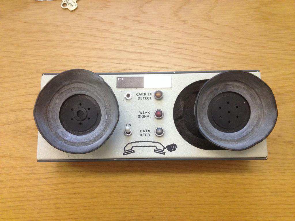
The last two months have been rather quiet on the acquisitions front. We have received an acoustic modem in excellent condition to replace the rather tired one originally on display, a partial CE toolkit in poor condition, some portable PCs and various pieces of documentation. 2984 CashPoint Model
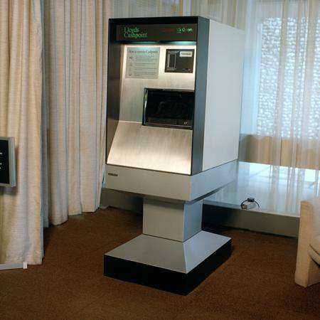
We have started work on building a semi-scale full size model of the 2984 Lloyds CashPoint. We seem to have exhausted the possibility of finding a real one so this is the next best thing! We have an original instruction plate and some photos that help us to gauge the dimensions, but we don’t have any detail pictures of the keyboard area. We are also unsure of whether there was any form of display to guide users through the process, or whether they just had to follow the instructions on the metal plate, and have sent out an appeal to our retiree community for assistance. Analogue Computer Identified
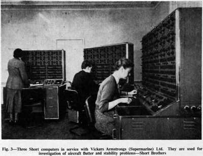
Thanks to the CCS, specifically Dik Leatherdale and Michael Brisk, we were able to identify analogue computers used by Vickers Supermarine during their time at Hursley in the 1950s. The original caption reads “Three Shorts computers in service with Vickers Armstrongs (Supermarine) Ltd. They are used for investigation of aircraft flutter and stability problems“. |
|
Ferranti Argus (Blodhound) — Peter Harry Following the completion of the restoration program for our Argus 700 it has continued to run reliably. The final task of converting the disc system from a FINCH disc interface to SCSI-2 and then to a SCSI-2 CF card disc emulator has also removed the vulnerability of the Argus relying on a single and very suspect FINCH, 5” Winchester disc. I have nothing to add regarding our Argus 700 other than one problem was resolved by a simple pull and reinsert of an I/O card rack. Another edge connector clean required using DeOxit! Attention has now turned to the ongoing support needed to ensure the Argus 700 will run in perpetuity which currently means:
Progress on these two fronts has already been made with a test set being developed to carry out static testing of the logic (74 Series TTL devices) on the Argus 700’s Parallel to Serial PeriBus converter (ME186). Secondly, work is underway on a Serial PeriBus emulator which will allow the dynamic testing of the I/O system and specific cards within it. An Arduino is being used to emulate the I/O timing from the Argus 700 which initiates PeriBus communication. (PeriBus connects the Argus 700 to its I/O interface cards). We do not have the timing data for initiating I/O on the Argus 700 so a bit of guesswork and trial and error is needed but progress is being made. |
|
Software — David Holdsworth Leo III — Intercode and Master Routine A new Windows binary version of the emulator has been made available. This one is compiled with Visual Studio 2010 SP1. It is to be found in leo.settle.dtdns.net/LeoCode/bin/ There is a set of 3 demonstrations of the software, each of which is described in the readme.htm file in both of sw.ccs.bcs.org/leo/LeoIIIdemo.zip and sw.ccs.bcs.org/leo/LeoIIIdemo2.zip. We have a volunteer Mike Tyzack who is searching for Leo III magnetic tapes that may have been retained as souvenirs. This is in the hope of finding binary versions of Leo III software (especially CLEO). If sufficient numbers are identified, we will investigate further the prospects for reading them. We are confident that the software system that we have resurrected so far will able to process them. KDF9 — Kidsgrove Algol Compiler On 6th November Brian Wichmann relayed this message from Bill Waite in the USA: “As to your KDF9 question, I have all of my manuals and a complete listing of the Kidsgrove Algol Compiler plus some other Usercode programs. I don’t believe that I have any machine-readable source, but I’d have to fossick through old media to be certain.” We are busily exchanging emails about how best to resurrect Kidsgrove Algol from these listings. They have been scanned in the States and the scans can be seen here at sw.ccs.bcs.org/kalgol.src/index.html. The print quality seems to be very good, and we are hoping that it will prove possible to use OCR rather than copy typing. We have a new version of Bill Findlay’s KDF9 emulator (V2p0r) which can be found at www.findlayw.plus.com/KDF9/emulation/emulator.html. It has been put into service in our on-line Whetstone Algol facility kdf9.settle.dtdns.net/. Compiler-Compiler — Dik Leatherdale After a long period of inactivity the Compiler Compiler project has taken a leap forward. Compiler Compiler is not, of course, the easiest system with which to come to grips and much of the contemporary published literature understandably deals with the then novel aspects of the system without considering the language as a whole. But a couple of years ago we became aware of Introduction to Compiler Compilerthe late Brian Napper which sounded as if it might be useful. Sadly our enquiries failed to find a copy of what must have been a fairly esoteric and rare publication. Then a couple of months ago John Davies offered a copy to the University of Manchester and the University (in the person of Prof. Jim Miles) in turn, kindly lent it to me. I have OCRd it and Bill Purvis has heroically proof read it. It is indeed just the job for beginners such as ourselves and is the encouragement we need to progress matters further. You can find it at tinyurl.com/ccbynapper. It will be interesting to see if it sheds any light on Edinburgh’s Atlas Autocode / IMP compiler which we suspect is at least inspired by Compiler-Compiler. There is some reference to this at sw.ccs.bcs.org/KDF9/AA.html. |
|
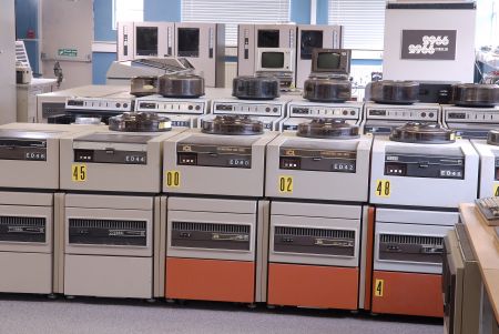
ICL 2966 — Delwyn Holroyd
Work over the last few months has mostly been concentrated on the two GTS2 tape decks. Both decks now read and write in PE and GCR modes. We have learnt that frequent cleaning is required for reliable operation, probably because the scratch tapes we are using for testing are shedding a lot of oxide. In particular the capstan on MT11 is very sensitive to oxide build up which results in tape slippage and read errors. The tape head and write amplifier on MT10 were swapped with one of the other decks due to a shorted write channel. One of the read channels in MT10 was found to be picking up noise from the servo system in the deck, causing frequent retries. This was cured by swapping the read pre-amplifier board. The replacement was then found to have an open circuit capacitor. Reading is now much more reliable. The restored decks are tri-mode, but unfortunately there is a fault in the NRZI board in the formatter, and the spare board proved to be faulty as well. We are still hoping to locate a copy of the schematic diagrams for these decks (STC 1960) so that we can undertake board level repairs. Most of the restoration work was done with the decks connected to a PC via our ‘New Range Peripheral Interface’ box. This greatly simplified the fault-finding and adjustment process because any desired sequence of commands could be issued, and detailed sense information from the deck examined. The PC software was further developed to enable real tapes to be captured as files and real tapes to be recreated from virtual ones. We now have good copies of all the 9 track tapes in our possession and have even been able to complete a few special commissions, including recovery of the source for two books on computer languages. The latter were recovered from TAR format UNIX tapes written over 30 years ago. The final stage in the restoration was completed at the beginning of November. Having created a real copy of the 1900 engineers’ library tape (from a virtual image made over 15 years ago), the decks were hooked up to the 2966. From a George job the magnetic tape test programs #RMTA and #TMTA were loaded from the engineers’ tape. Two work tapes were then created and the test programs run. Both sets of tests completed successfully. Alan is working on bringing our restored EDS80 back to life following a head crash some time ago. He is also creating a demonstration of how discs work based on a partially disassembled EDS200 drive turning at low speed. A power supply fault on one of the 7181 VDUs has been (probably temporarily) cured by taking it apart and putting it back together again! The machine is generally operational every Thursday and Saturday. We are looking for more volunteers to expand the team to allow regular operation on Sundays as well. |
|
Analytical Engine — Doron Swade The bicentennial year of Ada Lovelace’s birth falls this year. Preparation for various celebratory events has directed attention to Ada Lovelace’s ‘program’ (1843) to calculate Bernoulli numbers using Charles Babbage’s unbuilt Analytical Engine. A small group including Tim Robinson in the US, Rainer Glaschick in Germany, Bernard Sufrin in the UK (and me) have been collaborating in exploring the ‘program’. Significant progress has been made with many obscurities now illuminated. The study has directed new attention to how the several types of punched card control the internal microprograms on the one hand, and how these functions interface with the user on the other. There has been significant archive activity. The major historical source is the Babbage technical archive held by the Science Museum. The Science Museum digitised the archive in 2012 is now preparing to provide open access to the archive. The Analytical Engine project team has been the main user of the digitised archive under special licence. In the course of the project mismatches have been identified between the digitised material and the existing printed index compiled by the late Allan Bromley and published by the Science Museum in 1991. Referencing anomalies, identification of material omitted from digitisation exercise and other structural issues have become evident. Descriptions of these have been compiled and we are working with Science Museum archivists to resolve and correct these ahead of open access release. The work is detailed and, given the volume of material, substantial. Eye-strain is an ongoing hazard. This archive work has suggested a new and significant prospect for the role of the Notation in an understanding the designs. One of the difficulties in understanding the designs is the need to reverse engineer logical function from mechanical drawings of mechanisms - this without textual explanation of purpose or intention. The original hope was that the notations, expressed in Babbage’s symbolic descriptive language, would contain a higher-level logical description that would relieve this difficulty. As described in earlier reports the main features of the Notation were decoded from a detailed knowledge of the mechanisms of Difference Engine No.2. The provisional conclusion from that study was that the notations are a description of the mutual physical relationships of mechanical parts and are not an abstraction of a logical description of the Engine’s function. Further, that the mechanical design preceded the notational description. New material found in the archive suggests that while this might be true for Difference Engine No.2 the notations for the Analytical Engine (about 2,700 of these) may indeed embody higher-level logic, control functions for sequencing the punched cards and orchestrating the internal operations that the punched cards control. If so, the notations would provide the explanatory tool we have been looking for and the prospect of this is enough to distract one from the plight of refugees migrants and austerity, even if only briefly. |
|
Science Museum — Katherine Platt The Museum has recently opened a new facility for researchers. Its library contains a huge volume of the literature of Science and Technology. Some of this material, the Open Access Collection, is held at the Dana Centre in London and is available on demand, but much of the collection is held at the Museum’s storage centre at Wroughton and must be ordered well in advance. Details of the facility can be found at tinyurl.com/scmlib and the catalogue is also online at tinyurl.com/scmcat. |
|
Our Computer Heritage — Simon Lavington & Rod Brown The re-designed OCH website went live on 22nd August. The URL remains the same but the site is now compatible with the look and feel of the main CCS site. The current site is a used facility and the work to make it compatible whilst promoting the CCS as an organisation is worthwhile. It remains a work in progress whilst new content is produced. |
North West Group contact details
Chairman Tom Hinchliffe: Tel: 01663 765040.
|
News Round-Up
|
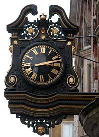
For many years past the Science Museum has been the venue for our London meetings in the delightful surroundings of the Fellows’ Library. Sadly the building has now been sold and we must make new arrangements. Starting with our March meeting we will be at the London premises of BCS the Chartered Institute for IT in the Davidson Building, 5 Southampton Street, London WC2E 7HA. The Davidson Building is a short walk southwards (downhill) from Covent Garden Underground Station, straight through the old market and into Southampton Street. Once there, the BCS is less than easy to identify. The entrance is adjacent to the Cotswold outdoor clothing shop. Look for a beautiful, ornate clock (see above) on the east side of the street. The door under it is the one you want. If you ask at reception they will tell you that the BCS is on the first floor. We look forward to seeing you there and, perhaps making new friends in our new London home. www.bcs-kidmm.org/locations/bcs-ss.html gives a more comprehensive set of directions.
Meanwhile you might like to join us for our very last meeting at the Science Museum in February which will (fittingly) be delivered by our co-founder and former Science Museum curator, Doron Swade. Come to sample the twin pleasures of listening to Doron and admiring, for the last time, the handsome room which has hosted us for so long. Shed a little tear perhaps. Our sincere thanks to the Science Museum for their past generosity.
101010101
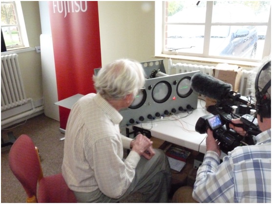
We were delighted to hear that Fujitsu has become a “Foundation Sponsor” of the National Museum of Computing (TNMoC) and is taking an active interest in its (ICL) history for the first time in many years. Alan Thomson has been instrumental in persuading Fujitsu to make this move and he and John Williams, Fujitsu UK’s head of Marketing Services, are to be congratulated on making this most welcome development possible.
101010101
The 2016 reunion of our good friends the LEO Computers Society will be held on 10th April in London’s Middle Temple Hall no less.
Details at www.leo-computers.org.uk.
101010101
It is planned to visit the Berlin Technical Museum on 15th-17th April 2016 to view, amongst other things, the replica Z1 automatic mechanical calculator built by Konrad Zuse. Our host will be Prof. Horst Zuse who has memorably spoken at CCS meetings on the subject of his father’s work.
The plan is to travel to Berlin on Friday 15th April and to gather for dinner that evening. Saturday would be spent at the museum followed by another group dinner, returning on Sunday. You should make your own arrangement for travel and hotels but it is suggested that hotels near Alexanderplatz would be convenient.
If you are intending to come, please contact Dan Hayton at daniel@newcomen.demon.co.uk.
101010101
The recently-celebrated bi-centenary of Ada Lovelace (see the previous edition of Resurrection) has rather overshadowed that of George Boole a few weeks earlier. A pity, as Boole’s work on mathematical logic is, arguably as important as the rather better-known work of Lady Lovelace. A good summary of his achievements can be found at https://en.wikipedia.org/wiki/George_Boole.
101010101
Back-issues of Resurrection have been relocated to the main CCS website where they will be easier for us to maintain. If Chris Burton and I have done our jobs correctly browsers will not notice any difference.
A new section of the CCS website is slowly being created to host our collection of emulators of historic computers and accompanying software. www.computerconservationsociety.org/software/software-index.htm will be our “zoo” so to speak. All contributions welcome of course.
The Baby Baby or An Extremely Small Scale Experimental MachineDave WadeThe Baby Baby is a reduced-size, implementation of the Manchester Baby or Small Scale Experimental Machine (SSEM) written in VHDL and implemented using a Field Programmable Gate Array (FPGA). I use the term “implementation” as opposed to “emulation” as I feel this better expresses the intent of the project. Emulation often implies that some existing computer is re-programmed to reproduce another machine and in this case there isn’t another computer. Objectives There were two main objectives in building the Baby Baby:-
Improving Knowledge of the Baby I am Computing Volunteer at Manchester’s Museum of Science and Industry (MSI) where my role is to demonstrate and explain the workings of the replica Small Scale Experimental Machine, or “Baby” for short. The Baby is a popular exhibit so there is little time for hands on training whilst at the Museum, yet I felt that to be an effective explainer I needed to know more about the machine. Improving Field Programmable Gate Array coding skills I had seen and used a number of FPGA re-implementations of historic computers, including ENIAC, IBM/360, IBM/1130, PDP/8 and PDP/11. Whilst I had a basic knowledge of how to configure FPGAs, I did not fully understand how they could be used to implement a computer and wanted to explore this in more detail. It seemed that both the above could be achieved by building a Baby Baby using an FPGA to implement the CPU. .The MSI Baby Replica The original Small Scale Experimental Machine (SSEM) or Baby was the first computer to run an electronically stored program in RAM. A full sized operational replica of this is on display at the Museum of Science and Industry (MSI) in Manchester. The replica at MSI is intended to implement the machine as it was at the date of running the first program. In this project I have attempted to reproduce this on a smaller scale. The Logical Design Architecturally SSEM has a 32 bit word with a fixed format instruction. The term “line” is used to describe a word in storage, as each one maps to a line of dots and dashes on a CRT tube. There is a 5-bit address field, allowing 32 lines to be addressed and a 3 bit operation code, which would allow eight instructions but in fact only seven are implemented1:-
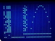
This leaves most of the 32 bits unused. Some of the demonstration programs “borrow” the unused bits either as storage or to display information. For example here is the output of a program running on the Baby Baby which uses difference statements to plot a quadratic:- The machine is Turing complete even though there is no Add instruction, only a Subtract, meaning addition requires two instructions. Physical Implementation Physically SSEM consists of 6 racks, each of which is 19” wide and over 6’ tall. In addition, and partially hidden, there is a seventh rack containing the power supplies. There is an 8th shorter rack which contains a large Desktop PC used to load programs into the Baby. Electronically it is implemented using thermionic valves as the active components. There are 300 diodes and 250 other valves, mainly EF50 pentodes in the machine. Whilst it is entirely electronic it is not entirely digital and analogue circuits are used in several places, especially to generate the CRT sweep voltages as described below. It also uses an analogue adder and subtractor. It stores information as static charges on the rear or inner surface of Cathode Ray Tubes (CRTs) which are scanned line by line as in a traditional television set, giving a serial implementation. Such stores are known as Williams or Williams/Kilburn tubes after their inventors. It had three such tubes:-
As the CRTs used need careful adjustment to operate, the MSI Replica also contains a semiconductor store that can be used to allow it to be reliably demonstrated. There is a fourth CRT tube which is called the “monitor tube” and it can be switched to display the image from any of the other three tubes. There is a single bulb which lights when the machine executes a Stop instruction. The STOP instruction also sounds a hooter. These are the only output devices on the machine. All output is displayed as a bit pattern and any numbers must be converted to decimal, octal or hexadecimal by hand. The machine is synchronised to a master oscillator running at 100 KHz. This is used to generate an asymmetric clock with 6µsec / 4µsec period. This is referred to as the “DASH signal” and results in a bit clock time of 10 µseconds overall. Each store access takes 36 of these pulses, 32 for the actual access when the CRT beams move forward across the tubes and four to allow them to fly back. This is known as the “BLACKOUT” period and is marked by a “BLACKOUT signal”. Each instruction takes four sweeps of the tubes to execute giving an instruction time of 1.44 msec, these sweeps are known as “Beats” and are labelled “Scan1”, “Action1”, “Scan2”, “Action2”. The type of beat (Action or Scan) is defined by the HA and HS signals which are derived from the BLACKOUT signal. The operation of the machine in each beat is as follows:-
This means that the main store is refreshed twice per instruction. The line to be refreshed is defined by the C counter. This is a 5-bit counter its bits labelled “C0” through “C4” and which is incremented by HA signal. The P-Pulses and Staticisors A “staticisor” is the terminology used in the MSI replica documentation for what today we would a “latch” or “register”. It is a small memory constructed from valve bi-stables. The MSI replica has two, a 5-bit latch called the “line staticisor” or “L-Stat” and a 3-bit latch called the “function staticisor” or “F-stat”. The L-stat is used to store the address of the line in memory that is to be accessed, and so drives the main store Y-amplifiers during an Action beat. The F-stat stores the 3-Bit operation code and is used to control the flow of data during the Action2 beat. The appropriate bit of data from the serial word is gated into the staticisors by means of signals called the “P pulses”. There are 32 P pulse signals P0 to P31 one for each bit of a line. They are generated by the DASH signal which in effect clocks a pulse along a shift register, making the signal Pn active when Bit n of a line is passing through the machine. P0 through P4 are used to gate the address into the L-stats and P14-P16 are used to gate the function code into the F-stats. They are also used in conjunction with the Typewriter Buttons described below to allow store to be manually changed. The PC Interface The external PC interface works by intercepting the store refresh loop. The C4 and DOT counters are fed to the PC along with the current bit from the store. The PC interface uses the C4 counter to determine when a refresh cycle has started, and by counting the DOT pulses it can keep track of which bit is being output, and so can continually read the MSI replica store. In order for the PC to write data into the STORE two further signals are provided on the PC interface, a “WRITE” and a data line which allow the PC to write the MSI Replica Store. An additional Output from the MSI Replica to the PC allows the write to be controlled from the MSI Replica front panel. The Switches The full size Baby has around 50 active buttons and switches on three panels as follows:-
The Field Programmable Gate Array (FPGA) Xilinx which makes the Spartan 3E chip I used describes an FPGA as follows:- “Field programmable gate arrays (FPGAs) are semiconductor devices that are based around a matrix of configurable logic blocks (CLBs) connected via programmable interconnects. FPGAs can be reprogrammed to desired application or functionality requirements after manufacturing.” So, a matrix of configurable logic that can be connected in many ways, but what are CLBs? Configurable Logic Blocks Configurable logic blocks or CLBs are the bricks which are used to implement a given logical function within the FPGA. These may contain a number of different logic elements including adders, flip-flops and multiplexors. They are configured by look-up-tables (LUTs) that are small RAM modules which can be programmed to simulate a logic gate. For example a 4 × 1 bit memory will have two address input lines, conventionally labelled A0 and A1 which select the CELL to be read or written, and an output, say D0 where the content of the selected Cell can be read. By storing appropriate data in each of the four cells it can emulate any 2-input gate. If the RAM is programmed so all the cells contain 0 except that at address 11 which contains 1 then it implements a 2-input AND gate as the truth table below shows:-
By loading the LUTs with suitable data the CLBs may be programmed to perform a wide range of logical functions. The matrix of programmable interconnects allows these to be connected so that a complex logic system can be created. A typical FPGA contains thousands of these cells and logic to interconnect them so that complex systems may be produced. In addition FPGA chips may contain other logic circuits, for example dedicated multipliers and general purpose RAM. They also contain I/O buffers which are used to connect the chip to the outside world. The Spartan 3E and the NEXYS 2 board I have implemented the Baby Baby on a Digilent Nexys 2 board that I had been using for other projects. This is a general purpose prototyping board containing:-
This board is rather over-specified for implementing the Baby and only about 10% of the available resources are used. Configuring the FPGA With chips containing thousands of logic cells a design tool is needed to convert logic descriptions into bit patterns. Xilinx provides a library of tools called “ISE” to perform this translation. Whilst it is possible to input logic diagrams with gates and interconnects into this tool this is a tedious and error prone task. Instead most FPGA designs are written in a hardware description language or HDL which resembles a traditional programming language. As with a programming language several source files may be combined to create single logic system. Once the HDL has been input a process called “Synthesis” produces a list of the gates and connections that will implement the HDL. The output from the synthesis step is then mapped onto the CLBs and programmable interconnects in the chosen FPGA to produce a physical layout. This is then used to create a programming file or bitstream, that is loaded into the FPGA at power on. An introduction to VHDL There are two standardised HDLs, Verilog and VHDL. The Baby emulator is written in VHDL as I was more familiar with this. VHDL has military origins and was originally developed for the U.S Department of Defense in order to document the behaviour of Very High Speed Integrated Circuits (VHSICs) and so it is the VHSIC hardware description language. Its syntax is based on ADA but as ADA is one of the few programming languages I have never encountered in 43 years of programming I can’t comment on this. VHDL was first standardised in 1987 as IEEE 1076-1987 and has undergone several revisions since. Whilst it was originally used to document existing behaviour, it was soon realised it could be used to generate logic simulations of the chips it was describing. Later the design flow was reversed and rather than use VHDL to document existing designs, VHDL became the design language. The tools provided by the manufacturers of FPGAs support both chip design as described above, and logic simulation and so designs can be tested and debugged before being programmed into an FPGA chip. In order to use the simulation feature, additional VHDL modules are written which specify the behaviour of the external interfaces. This code is generally non-synthesisable, so whilst it can be used by the simulator to test the system being designed, it cannot be translated into logic that can be used to configure the chip. This distinction is important as it is a common misconception that FPGAs can dynamically reprogram themselves. Whilst there may be special cases where this does happen, in general once the VHDL has been translated the code is loaded into the FPGA at power up and the gate configuration remains constant until it is powered off or totally re-programmed. This is the first part of a two-part article, the rest of which will appear in the next edition of Resurrection. Dave Wade is a volunteer on the replica SSEM at the Museum of Science and Industry in Manchester. He can be contacted at dave.g4ugm@gmail.com. |
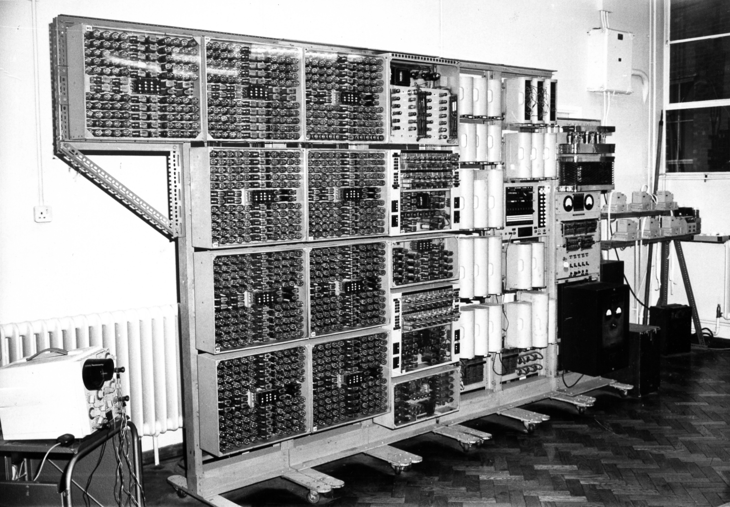
Memories of WitchMike TeddThe Harwell Dekatron Computer at The National Museum of Computing (TNMoC) is the world’s oldest working computer. There are working replicas of earlier machines, but this is the genuine article, lovingly restored to working order at TNMoC in Bletchley Park. It was designed and built at the UK Atomic Energy Research Establishment at Harwell between 1950 and 1952 and used there for several years.
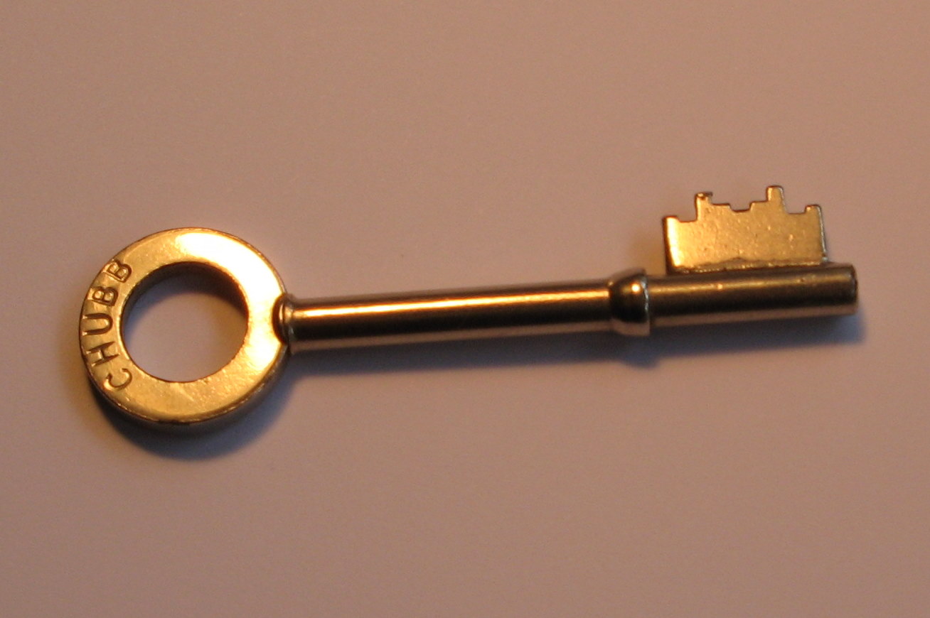
When Harwell retired it from active use, a competition for the best future use was won by Wolverhampton and Staffordshire College of Technology where it was rechristened WITCH (“Wolverhampton Instrument for Teaching Computation from Harwell”). It later moved to the Birmingham Museum of Science and Industry which closed in 1997, and spent some years lost in storage before being rediscovered in 2008, moved to TNMoC and restored to working order by November 2012 — already 60 years old! In late 1960 I and a fellow pupil, Peter Burden, were coming to the end of our school careers at Wolverhampton Grammar School. We were in the third-year sixth and had won scholarships to Cambridge. The school was understandably keen to keep us until the day when pupil numbers were counted for their funding so needed ways to keep us happily busy. It was suggested that we spent time at “The Tech” playing with WITCH. What an eye-opener it proved to be! WITCH is an essentially decimal machine. The electronic storage is based on 10-state valves called Dekatrons — just 90 stores, each holding an 8-digit decimal number. Instructions are normally held on five-hole paper tape and read and obeyed from one of six mechanical readers. The small instruction repertoire includes instructions like “conditional transfer to reader number 5”. Control sequencing, arithmetic etc. are undertaken by logic arrays built out of relays. Simple instructions thus take about two seconds and multiplications much longer, so the computer was incredibly slow by modern standards; humans can work faster, but they need to eat and sleep and they make more mistakes. The design has some real advantages. The state of a Dekatron valve is visible, so one soon learned to read the contents of the store; together with a single-step control this made debugging easy. One also developed skills in reading, splicing and patching paper tape which I found useful later at Elliott Automation and Computer Technology Ltd. Although reliable for its time, WITCH did break down every few days. I remember that one of the cleaners undertook first-line maintenance, typically by cleaning contacts and replacing valves. The idea of a ‘loop’ in a program took on a physical form for WITCH. A piece of code executed multiple times would be punched onto tape which would be glued into a loop held in one of the readers. Unfortunately the readers used metal pins to sense the holes in the tape, so after a while (100 or so travels through) a pin would force through the tape, and the program would typically crash. The main technique to address this involved calculating how often the code would be used and replicating the code a suitable number of times in the loop so that each area of tape was read fewer times — my first introduction to algorithm analysis! The resulting loops of tape could become quite large with a danger of getting tangled, so they had to be arranged round strategically placed nails near the readers. In extremis one could use plastic (Mylar) tape which lasted longer but was expensive. One could put a few instructions into the Dekatron store but space there was very limited, and instructions took even longer to execute from store. After a few small programs to get us going, Peter and I were handed a real project. The local lock manufacturer, Chubb, wanted us to help them design locks. Actually it was to list acceptable keys — they used the list to cut each key and then made a lock to fit the key. Each key (see picture) consisted of nine columns, the height of each column defined by a digit; since the key was symmetric (so it could be used either side of the lock) each key code was a five digit decimal number. Chubb wanted a list of all the codes for sensible keys - for example ruling out keys with adjacent columns of the same height and keys where one column projected too far thus making it liable to break off. Developing the program took us a few days, but it ran very slowly, so lots more effort, mainly Peter’s, went into polishing it to run faster as well as tackling the problems of tape failure. I seem to remember the final ‘production’ run took about 30 hours — for a job that would take less than a second on a home computer. The local paper, the Express & Star, picked up the story of this program and ran an article on May 27th 1961. Headlined “WITCH AND TWO BOYS SOLVE KEY PROBLEM”, it started “Electronic computers, you would think, are fearsome things. Not the sort of instruments which grammar school boys, even sixth formers, should be expected to master.” Chubb was very grateful and took us out for a slap-up meal.
Peter and I then put computing on one side and studied mathematics, although both of us eventually chose academic careers in computing, perhaps inspired to some extent by this early experience. For me, when I moved to Aberystwyth in 1972 it was a delightful surprise to be given the pictured key, for the building housing my office, which was designed by our program. Mike Tedd retired from the University of Wales, Aberystwyth where he was head of the Computer Science department and, for a period, Vice-Principal. He can be contacted at mike tedd@aber.ac.uk |
CCS Website InformationThe Society has its own website, which is located at www.computerconservationsociety.org. It contains news items, details of forthcoming events, and also electronic copies of all past issues of Resurrection, in both HTML and PDF formats, which can be downloaded for printing. We also have an FTP site at www.cs.man.ac.uk/CCS/Archive, where there is other material for downloading including simulators for historic machines. Please note that the latter URL is case-sensitive. |
Elloitt 903 Music
Andrew Herbert
Like many machines of its era (mid 60s—mid 70s), the Elliott 903 (a.k.a. Elliott 920B) had a loudspeaker to give audible feedback on program execution. A running program produced a varying warble, a dynamic stop a high-pitched whistle and a stopped machine, silence (apart from the steady whirr of the fans). Inevitably programs were written to play musical tunes by executing carefully tuned sequences of instructions. (The concept of a sound card didn’t exist at that time, and although a 903 could be fitted with a digital to analogue converter, this was not common and providing one to just play tunes for amusement would have been considered profligate.) As part of my project to collect Elliott 900 software, several music programs have been found. Most have been resurrected sufficiently to be able to test them and make comparisons, the findings of which are reported here. The Hardware The audio tone output by the loudspeaker is dependent on the repetition rate of the computer’s “VTG” waveform. The VTG pulses control a relaxation oscillator in the computer control panel that in turn drives the loudspeaker. The frequency of the oscillator depends upon the VTG pulse repetition rate, which in turn depends upon the sequence of instructions obeyed and the time they take to execute. VTG is pulsed twice in most instructions, three times by function 6 (collate) and just once by function 14 (shift). Order 1 (add) typically takes 24 µsecs, order 13 (divide) 80 µsec. To produce a scale of musical notes, wider spacing of VTG pulses is required than that offered by differences between individual instruction times. Salvation lies with instruction 14 n that shifts the accumulator n places left. The duration of the instruction is 22+3n µsecs, i.e., the larger the value of n, the greater the spacing before the first VTG of the next instruction. In the machine specification n is required to be between 0 and 48, higher addresses being reserved for various forms of I/O transfer. In practice, on the 903/920B, n can be as large as 2047 and this is sufficient to allow a musical scale to be constructed. The simplest tone generator is a loop that includes a 14 instruction giving sufficient delay for the burst of VTG pulses to make the control unit oscillator circuit emit the desired note:
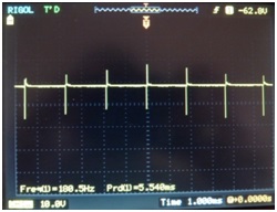
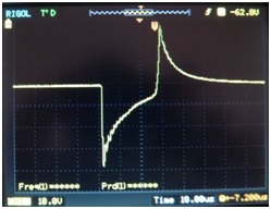
DURATION is assumed to be a store location that contains a negative count of how many loop cycles are required to emit the tone for the required duration. The desired tone is obtained by choosing an appropriate value for NOTE. The two images below show typical oscilloscope traces for the signal sent to the loudspeaker recorded on my 903. The first image shows a train of pulses arising from a loop as described above: the distance between the spikes is the delay due to the 14 instruction. The second shows a single pulse in more detail.
Similar results were obtained from the TNMoC and CCH 903s, although with these there was a lot more noise between the pulses. In particular the TNMoC machine shows significant breakthrough every third cycle. On my 903, NOTE=108 produces A5 (220Hz), NOTE=36, A4 (440Hz), NOTE=1, A3 (880Hz). Other 903s perform quite differently. The table below show the shift values for a chromatic scale on my 903, the CCH 903 and the TNMoC 9032. .
The table was produced by connecting an oscilloscope to the loudspeaker of each machine and adjusting the shift count (NOTE) until a value was found that produced required frequency for each note in the scale. The rate of instruction execution increases (by as much as 10%) as a 903 warms up. It is best to calibrate a machine after it has been computing hard for 30 minutes or more. 2. [“AJH” here refers to the author's 903, “TNMoC” to that at The National Museum of Computing and “CCH” to the one at the Centre for Computing History at Cambridge] It might be thought that the differences between the machines is simply one of transposition, but lining up the sequences on values of NOTE shows this is not so:
In principle the pulse repetition rate driving the relaxation oscillator can be calculated: PRR = loop time + n * unit shift time, where loop time is the time to execute a loop containing 14 0 and unit shift time is the increment for each additional place shifted. (Nominally loop time is 96µs and unit shift time is 3µs, but variations of up to 10% from these figures have been measured on individual machines). If the emitted note was proportional to the pulse repetition rate, the repetition rate for notes one semitone apart should be in the ratio 21:12. Taking pairs of notes and solving simultaneous equations reveals that this is not the case and so the frequency produced by a loop cannot be easily predicted mathematically. Consequently each machine must be tuned by measurement. No wonder then that programs which sound tuneful on one machine sound dreadful on others. Writing Music Having found a means to play notes, the next requirement is to devise a means of representing a tune. For each note to be played we need to specify a value for both NOTE and DURATION and if we want to specify absolute durations, we have to calculate the number of loop cycles to be executed, based on the value of NOTE. The most direct input format would be <NOTE, DURATION> pairs, but this would require the “composer” to both remember the NOTE values and compute correct values for each DURATION. Better to have a textual notation giving the name of a note and its duration in some time unit, e.g., C1 meaning 1 unit of middle C. To cover several scales a notation for octaves is useful — e.g., upper case and lower case letters for a low and high register, or perhaps a symbol such as ^ to specify one octave above, ^^ two octaves above and so on. Similarly a suffix notation for sharps, e.g., # and flats, e.g. @ could be provided. Other useful things to denote are rests (pauses), slurring (notes that run into one another rather than being separately voiced) and repeated sections. The Recovered Programs MUSIC This is a program I remember hearing as a schoolboy when using the Elliott 903 at the Medway and Maidstone College of Technology, and again as a student at Leeds University. It comes with three tunes: Rimsky-Korsakov’s Flight of the Bumble Bee, Mendelssohn’s Wedding March and Handel’s Arrival of the Queen of Sheba. An original source version of this program has yet to turn up, but the Elliott 903 paper tapes at TNMoC included two store dumps of the player and a source has been reconstructed from these. It is believed the dumps originated at Aldenham School. The program consists of a translator and a player. The translator reads in a textual score and punches tape of integer <NOTE, DURATION> pairs as decimal numbers terminated by a halt code. The player then reads the output tape back in; the numbers are stored; and, on reaching a note of -1, the tune is played. At the end of the tune, the player then attempts to read in another tape. The tune tapes are quite large as the numbers are punched in space-aligned columns. In the textual input, pitch is expressed as a letter A-G, possibly followed by one of more ^ symbols to raise the pitch by one or more octaves, ′ to sharpen by a semitone or @ to flatten. The duration is an integer representing units of about 10ms. The letter S terminates the input. The letter R causes a rest of about 1msec (and is translated to a loop of 14 900 instructions which produces a barely audible growl from the loudspeaker). Thus the beginning of God Save the Queen can be coded as: G3G3A3F′2G1A2B3B3C2B1AG3S It would seem the program was generally distributed in binary form and the tunes in numerical rather than textual format. No source for the program has been found, nor any tunes in textual form. Interestingly, constructing histograms of the notes in the recovered tunes revealed some differences in pitch values for notes than those embedded in the translator part of the recovered program. Subsequent to the first draft of this article a further version of this program has been found in Terry Froggatt’s collection. The original came from an Elliott 903 formerly belonging to Alistair McCowan & Associates in Pontefract, Yorkshire. (McCowan’s was part of the infamous Poulson organisation.) The tape is labelled TUNES (VARIOUS), FOR OLD 8K ONLY suggesting it came from a machine with an additional fast store. The code is positioned differently in store and has some minor coding differences from the Aldenham version but is otherwise identical. The tunes on the tape are, Men of Harlech, God Save the Queen, Auld Lang Syne, Ash Grove, Land of My Fathers and Land Lubbers Lying Down Below. Museum of Scotland (MOS) MUSIC A music tape was found in a collection of tapes at the Museum of Scotland associated with their stored 903. This tape has just a player part without any translator. It has The Sailors’ Hornpipe following on from the program. The program is in the form of a clear store followed by the Elliott relocatable binary loader, followed by the program in relocatable binary form (both as output by the SIR assembler), followed by the numerical form of the Hornpipe. The position of the program in store is curious, starting at location 434, a not particularly convenient entry point to set up on the control console. A conventional entry at 32 works as fortunately zeroed locations between 32 and 434 are effectively no-ops — instruction 0 just loads the B-register from itself in this context! The program closely resembles MUSIC, but the player loop is a little different in that it uses a B-modification to vary the shift (14) instruction rather than patching store. The pitch values in the Hornpipe tune do not correspond to those used in MUSIC, or indeed any of the other music programs I’ve found. MAESTRO This program is elusive — I have found documentation for it, written at Queen Elizabeth College, but no trace of any player. One tune tape, labelled Cockles and Mussels has turned up and is in a binary format. The documentation describes a comprehensive program with facilities for inputting and playing textual music, producing binary tapes and playing them, retuning the player and using the teleprinter as a keyboard for interactive music playing. The textual notation uses forms like A, BF, CS, AA for A, B flat, C sharp and A an octave above. Durations are specified by integers. God Save the Queen is rendered: G3G3A3FS2G1A2B3B3C2B1AG3S When played each note has a built in rest which can be suppressed by a following ½ character (i.e. slurred). A normal rest is coded by - (minus). Further features allow individual notes to be repeated (←), sections of music to be repeated, e.g., 5[ A2 B2 C2 ] (5 repeats of the enclosed sequence) and “procedures” declared and called, e.g. (PPP A2 B2 C2) ... PPP5 (declare procedure PPP and call it five times). In the description of how to use the tuning facility, it said that each note is a 50 word subroutine containing a loop of 40 instructions comprising a sequence of six 1 (collate) and 14 47 (shift) instructions, the pitch of the note being determined by the relative proportion of each. The tuning program allows the proportion to be varied and the total shift count to be increased or decreased. It might be thought this would allow a finer grained control of pitch than the simple loop of the MUSIC program, but the documentation that came with The Entertainer tape complains that MAESTRO is badly out of tune. This might just be due to difference in the instruction timing between machines, and indeed as some schools were donated the much slower 920A rather than the faster 903/920B, music tuned for one would indeed play badly on the other. Unfortunately there is no specification of the binary format so I’ve not been able to unpick the Cockles and Mussels paper tape. The MUSIC SYSTEM Also found at TNMoC was a short document describing a player called THE MUSIC SYSTEM, introducing it as an improvement over MAESTRO and giving a table of pitches and unit interval durations, different again from those in the MUSIC program. The operating instructions are as for the MUSIC program. A numerical format tape, labelled The Entertainer (i.e., Joplin’s piano rag used as the theme tune for the film The Sting) has been found with pitches corresponding to the table in the document. ALGOL MUSIC In addition to the version of MUSIC, two Algol 60-based music programs were in Terry Froggatt’s “Pontefract” set of paper tapes. The first program reads in tunes in textual form and punches out a tape of pairs of integers. The input format uses the same convention as MAESTRO, but does not include the facilities for slurring, repeats and procedures. The embedded pitch table is different again from that in other programs. No scores have been found corresponding to the table. This program remains an enigma. The second program reads in pairs of integers into two vectors in store and then calls a machine code procedure to play the notes. Before reading the notes, a first pair of integers is read, the first of which determines the number of notes in the tune and the second is a scaling factor for the duration of the played notes (like a metronome mark on printed music). The player follows the familiar form of the MUSIC program, except that B-modification is used to adjust the shift count rather than calculating and patching an instruction into the loop. By default three 14 2047 instructions are executed after each note played, unless the next note is of pitch 0, in which case the next note is played immediately (i.e. slurred). This is reminiscent of the description of the MAESTRO player’s features. To my ear, the pause between voiced notes makes the music sound stilted. A number of Christmas carols, folk songs and pop tunes were found in the numerical input format: some were clearly student experiments, others quite reasonable renditions of the tunes they claimed to be. One tune was identified with the author’s name: Karen Senior. Does anyone remember this name from their schooldays? TJF MUSIC This player has been the easiest to research as the author is well-known as the CCS rapporteur for Elliott computers. This program is interesting as it was written to run on a 920B with a digital to analogue convertor. If output via the convertor is requested, the program sends a sequence of amplitude values to the DAC that output a sine wave of the desired frequency. If output is via the loudspeaker the frequency value is converted to a shift count for the familiar shift loop. The shift count is merely a calculated value and therefore can only be related to the nominal frequency by external calibration. The input format consists of upper case letters A-Z representing successive whole notes and a-z representing the semitone succeeding the corresponding whole note, followed by a digit denoting duration. Thus a is A sharp, b is B sharp (i.e. C) and so on. It is also possible to specify octaves using + and - suffices, and $ for sharp. Input is terminated by a halt code. Writing scores as long lines of letters makes them very compact, although not so easy to read as the formats that uses octave, sharp and flat symbols. God Save The Queen can be rendered as: G3G3A3F$2G1A2B3B3C2B1AG3 or G3G3A3f2G1A2B3B3C2B1AG3S The program reads in the textual score and stores it in a larger buffer. The text is translated note-by-note on play out. The effect of this is to put a small “rest” between notes rather than slurring them together, making the music sound crisp. The value for each note is calculated using a table of frequencies for notes from which a shift count is calculated using the nominal instruction times for the play out loop. This means that the quality of the play out depends upon how closely the actual instruction times are to their nominal values and whether or not the emitted note is proportional to the generated VTG pulses. On my 903 it is tolerably ok, but on the TNMoC and CCH machines quite badly out of tune. TJF MUSIC comes with two tunes: one is a large collection of Christmas melodies, the other a tape called “Mandy’s Music” containing Clarke’s Trumpet Voluntary and Bach’s Jesu Soul of Man’s Desiring. A tape for God Save the Queen also exists, written for Her Majesty’s visit to TNMoC. AJH MUSIC Having explored the recovered music programs I set about making a music program of my own and producing scores for it that play all the recovered tunes. The input is basically TJF MUSIC format, but with the notes pitched an octave lower to give a larger musical range (3 octaves) and with A set to A6 (110Hz). Additional tokens include * to double the tempo and / to halve it, &n to reduce the tempo by a factor of 1.n and _ to play a rest. For the several collected tunes, using either the pitch tables from the relevant player, and/or constructing histograms of the pitches in each tune tape, I wrote a translation program to map to the notation and pitches of my player. My program has to be modified for each machine it is run on if the music played is to be in tune. The required shift counts for each note have to be determined by measurement and then inserted into the program data. In the case of the CCH and TNMoC machines music has to be transposed to be within shift count values that produce audible notes. There would be some difficulty in assembling a 903 choir given the mismatches and limits in musical range of the various machines. Conclusions This investigation of Elliott 903 music playing programs has revealed a surprising amount of (misplaced?) energy invested by 903 users in getting their machines to play barely passable tunes. Common elements included the use of a convenient textual format to capture the notes to be played and the need to tune the player to each different machine. Most of the music systems were very basic, but one included exotic features such as slurred versus voiced notes, repeats and even “procedures”. There are some gaps in the record. We have no source or binary code for MAESTRO and the documentation is insufficient to reconstruct it easily. We have an Algol music player with no textual input translator and another vice versa. We have the MOS player but no translator. If any readers can help fill these gaps the author would be pleased to hear from them. A recording of AJH MUSIC playing classical tunes can be downloaded from tinyurl.com/903music. Following an exciting and senior computing career Andrew Herbert is now Project Manager for the EDSAC Replica Project at TNMoC. He can be contacted at andrew@herbertfamily.org.uk. |
||||||||||||||||||||||||||||||||||||||||||||||||||||||||||||||||||||||||||||||||||||||||||||||||||||||||||||||||||||||||||||||||||||||||||||||||||||||||||||||||||||||||||||||||||||||||
40 Years ago .... From the Pages of Computer WeeklyBrian Aldous£1m 2903 order from Germany: A breakthrough in the highly competitive West German small systems market has been achieved by ICL with a single order, valued at more than £1 million, for 18 of its 2903 computers. The customer is Bauer Verlag one of Germany’s top publishing houses, which is an existing IBM mainframe user. (CW474 p1) First local govt order for 2900: The first local authority to go for an ICL 2900 is Lancashire County Council which is to have a 2970 system worth £1.3 million. The order was placed soon after the new range was introduced over a year ago and the machine is due to go live in April 1977. (CW474 p1) Scottish factory set up by DEC: Joining the ranks of US computer manufacturers with manufacturing facilities in Scotland, Digital Equipment Co has signed an agreement with the Scottish Economic Planning Department to open a factory on the Mosshill Industrial Estate, Ayr, about 30 miles from Glasgow. (CW474 p3) EMI updates scanner: A new version of EMI’s revolutionary brain scanner, claimed to be four times faster than the original model, has been announced by the company. At the same time EMI has revealed that sales of its CT5000 general purpose scanner, introduced in April, have shot up from 16 at the beginning of November to 40 with a total value of over £10 million. (CW474 p3) IBM’s satellite communications plan develops: The intention of IBM to carve a niche for itself in the satellite communications business took another step forward on December 22 with the formation of a new company, Satellite Business Systems, SBS. (CW478 p1) Multi display system from Computer Automation: A powerful multi display terminal/disc based system has been launched by the Computer Automation Commercial Systems Division, which was set up in mid-1975. Known as Syfa, it will enable mainframe users to establish networks of local computers. (CW478 p8) IBM PoS wins London Co-op order: A second UK order for IBM point-of-sale equipment has been placed. This time the buyer is the Royal Arsenal Co-operative Society in London. The sale includes 103 IBM 3653 PoS terminals, 16 IBM 3657 ticket encoders, two 3651 store controllers and at least three 32/75 VDUs. (CW480 p3) ICL’s first 2900 order in Australia: The first order for an ICL 2900 in Australia is for a 2970 valued at £1.15 million. The order was placed by an oil company, H.C.Sleigh Ltd, and the machine is due for installation this October in the company’s computer centre in Melbourne. (CW480 Int p19) Biggest 2903 goes live in Denmark: Implementation of the largest single ICL 2903 configuration is now nearing completion at the Danish Timber Co’s computer centre at Aarhus. The 48K system, valued at £250,000, has replaced 22 Singer invoicing machines. (CW480 Int p30) HP introduces high level language: A high level programming language, HPL, claimed to be as flexible as Fortran yet as easy to use as Basic, has been introduced by Hewlett-Packard with its latest programmable calculator systems. (CW481 p4) Rockwell closes Anita factory: Now considered little more than a nuisance, the Portsmouth based Sumlock Anita factory is in reality a monument to British inventiveness, for it was here that the world’s first electronic calculator, the Anita Seven, was invented and manufactured. (CW481 p15) NATO system based on 2960: Despite the fact that official announcement of the ICL 2960 is not expected until late next month, the first customer machine has already been installed at the NATO joint headquarters in Northwood, Middlesex, where it will constitute the heart of the Opcon command and control system. (CW484 p1) First university net goes live in SW: The first mainframe network in British universities has gone live in the south-west, where five ICL System 4 processors have been linked by 48,000 baud lines. (CW483 p7) Classroom Classic: The first Digital Equipment Classic computer in the UK has been installed at Oakham School in Leicestershire, and enthusiasm among pupils is such that they have taken over the running of the Computer Department. Neil Maycock, a seventh form science pupil. must be the youngest operations manager in the country, while fifth former Robin Merrett is helping to supervise the Junior Programming Society. (CW486 p1) IBM boosts power of 370/168 again: In the wake of the Amdahl challenge, which has already hit seven major 360 and 370 installations in the US and Canada, IBM has announced a further enhancement to the 370/168 only 10 months after it introduced the improved 168-3 processor. (CW486 p1) MoD approves DEC Coral 66 compiler: The final accolade of UK Government approval has been received by Digital Equipment’s Coral 66 compiler. The combination of compiler and PDP-11 hardware has been included on the Ministry of Defence’s list of approved machines. This follows assessment by the Ministry’s Inter-Establishment Committee for Computer Equipment. (CW486 p9) ICL installs 1,000th 2903: Amid great ceremony, ICL delivered its 1,000th 2903 last week. Only a brass band was missing as the £100,000 computer was wheeled from an ICL lorry into the Stuttgart headquarters of Wohnpunkt-Moebel Herbert Bock. (CW486 p20) |
Forthcoming EventsLondon Seminar Programme
London meetings normally take place in the Fellows’ Library of the Science Museum, starting at 14:30. The entrance is in Exhibition Road, next to the exit from the tunnel from South Kensington Station, on the left as you come up the steps. The February meeting will be the last at this venue. See News Round-Up for details of the new venue from March onwards For queries about London meetings please contact Roger Johnson at r.johnson@bcs.org.uk, or by post to 9 Chipstead Park Close, Sevenoaks, TN13 2SJ. Manchester Seminar Programme
North West Group meetings take place in the Conference Centre at MSI – the Museum of Science and Industry in Manchester – usually starting at 17:30; tea is served from 17:00. For queries about Manchester meetings please contact Gordon Adshead at gordon@adshead.com. Details are subject to change. Members wishing to attend any meeting are advised to check the events page on the Society website at www.computerconservationsociety.org/lecture.htm. Details are also published in the events calendar at www.bcs.org.
MuseumsMSI : Demonstrations of the replica Small-Scale Experimental Machine at the Museum of Science and Industry in Manchester are run every Tuesday, Wednesday, Thursday and Sunday between 12:00 and 14:00. Admission is free. See www.msimanchester.org.uk for more details Bletchley Park : daily. Exhibition of wartime code-breaking equipment and procedures, including the replica Bombe, plus tours of the wartime buildings. Go to www.bletchleypark.org.uk to check details of times, admission charges and special events. The National Museum of Computing : Thursday, Saturday and Sunday from 13:00. Situated within Bletchley Park, the Museum covers the development of computing from the wartime Tunny machine and replica Colossus computer to the present day and from ICL mainframes to hand-held computers. Note that there is a separate admission charge to TNMoC which is either standalone or can be combined with the charge for Bletchley Park. See www.tnmoc.org for more details. Science Museum :. There is an excellent display of computing and mathematics machines on the second floor. The new Information Age gallery explores “Six Networks which Changed the World” and includes a CDC 6600 computer and its Russian equivalent, the BESM-6 as well as Pilot ACE, arguably the world’s third oldest surviving computer. Other galleries include displays of ICT card-sorters and Cray supercomputers. Admission is free. See www.sciencemuseum.org.uk for more details. Other Museums : At www.computerconservationsociety.org/museums.htm can be found brief descriptions of various UK computing museums which may be of interest to members. |
Committee of the Society
|
Computer Conservation SocietyAims and objectivesThe Computer Conservation Society (CCS) is a co-operative venture between BCS, The Chartered Institute for IT; the Science Museum of London; and the Museum of Science and Industry (MSI) in Manchester. The CCS was constituted in September 1989 as a Specialist Group of the British Computer Society (BCS). It thus is covered by the Royal Charter and charitable status of BCS. The aims of the CCS are to
Membership is open to anyone interested in computer conservation and the history of computing. The CCS is funded and supported by voluntary subscriptions from members, a grant from BCS, fees from corporate membership, donations, and by the free use of the facilities of our founding museums. Some charges may be made for publications and attendance at seminars and conferences. There are a number of active Projects on specific computer restorations and early computer technologies and software. Younger people are especially encouraged to take part in order to achieve skills transfer. The CCS also enjoys a close relationship with the National Museum of Computing.
|
