| Resurrection Home | Previous issue | Next issue | View Original Cover | PDF Version |
Computer
RESURRECTION
The Bulletin of the Computer Conservation Society
ISSN 0958-7403
|
Number 70 |
Summer 2015 |
Contents
| New Arrangements for Resurrection | Dik Leatherdale |
| Society Activity | |
| News Round-up | |
| HEC2(M)-Keeping the Drum Spinning | Jeremy Wellesley-Baldwin |
| A Leo III: 21st Century Hindsight | David Holdsworth |
| Retro Computing with a Difference | Michael Brisk |
| 40 Years Ago .... From the Pages of Computer Weekly | Brian Aldous |
| Forthcoming Events | |
| Committee of the Society | |
| Aims and Objectives |
New Arrangements for ResurrectionDik LeatherdaleAs many readers will know, BCS the Chartered Institute for IT has generously funded the Computer Conservation Society since its inception over 25 years ago. In particular, it has funded the printing and distribution of Resurrection for the benefit of BCS members and non-members alike. With the growth of our Society in recent years, particularly amongst the non-members of BCS, not to mention the increases in postal costs and increased frequency of publication, the expenses associated with Resurrection have grown dramatically. Small wonder then that BCS has concluded that the present arrangements are no longer sustainable. Following discussions between CCS and BCS, it has been decided that members of BCS will continue to receive “free” printed copies of Resurrection after the present edition but non-BCS members will not. The exception to this is former members of BCS who are over 60 years of age and who had been members of BCS for at least five years. CCS members who do not qualify for a free copy may subscribe to Resurrection at a cost of £10/year via the CCS website, or may read Resurrection online where it will continue to be available to all without charge. It is our intention to announce the publication of each new edition to all members by email. If only it was so straightforward! Two problems have become apparent. The CCS membership records held on our behalf by BCS are somewhat incomplete and we believe that some ex-BCS members who qualify for a free copy have not been identified. If, as an ex-BCS member you have recently received from us an email, or letter assuring you that you will continue to receive printed copies of Resurrection you are safe. If you have not and you think you qualify then please get in touch with Dave Goodwin (dave.goodwin@gmail.com), our Membership Secretary who will try to sort matters out on your behalf. The second fly in this particular ointment is that we do not have email addresses for a substantial number of CCS members. This will prevent us from telling you when a new edition of Resurrection arrives. Again, if you receive occasional emails from us telling you about forthcoming meetings you are safe. Otherwise, please get in touch with Dave Goodwin and tell us. We apologise for this disturbance. We would prefer it were otherwise, but hope you understand the reasons for it. |
Society Activity
|
EDSAC Replica – Andrew Herbert We held a volunteers meeting at Bletchley Park on February 26th and April 23rd 2015 with about 20 attendees at each. The increment in chassis count since the last report is, of 142 total required: Designed 119->126; metal cut 118->126; built 90->97; Standalone test, 50->61. The standard flip-flop circuit has been redesigned to overcome problems found by John Pratt of false resetting induced by noise. The new design works much better and evidence to support its authenticity has been found on one of the “Loker drawings”. Chassis 01 (storage regeneration unit) commissioning is now complete. We have concerns about the circuits in terms of signals levels and breakthrough which may need further changes once we connect the units to the circuits that drive them. Les Ferguy is measuring the sensitivity of the units to input signal levels. John Pratt has completed the coincidence system and store interface as far as he can and awaits the clock and digit pulse system to be completed: it is ready to interface to main control and the store adressing system. A run of PCB “delay line simulators” is to be made up by Peter Isley so that we can have a working store to progress further. James Barr reports continued progress commissioning the order decoding system and has started work on constructing the main control sub-system. Nigel Bennée continues to progress the construction and commissioning of the arithmetic system. Chris Burton has researched the Display Units (for main store and “registers”) and has conducted some early design experiments. He is now making a detailed design. John Sanderson has constructed two clock / digit pulse distribution units: these are in service. John is now working on the initial instructions loading units. Alex Passmore has resolved some operational issues arising with the Power Supply system. One of the commercial power supply units failed and was returned to the manufacturer under warranty. No fault was found and it is back in service. Bill Purvis has been developing the FPGA EDSAC emulator so it can be used as a virtual reader and printer for EDSAC and also act as a surrogate for EDSAC should the replica suffer operational outages. Peter Linington has made progress with understanding the sources of echoes, distortion and attenuation in the prototype nickel delay lines. Building on this he now has a revised prototype under test that shows much less susceptibility to errors. Early discussions have started about how we will demonstrate EDSAC once working, to communicate the significance of the EDSAC programming system. We’d like to recreate the experience of the highly influential EDSAC Summer Schools. Thoughts are also turning to staging a high profile event when the machine is ready for a formal “opening” in 2016. |
|
TNMoC Members’ Club – Doug Neilson Some members of TNMoC recently met to restructure the Members’ Club. The Club will now be run BY its members and be self-supporting with a close relationship with the Museum. In March we held our first “new” members meeting and were pleased to have some 40 supporters with us at Bletchley Park. A small committee was formed at the meeting. The Members’ Club has two principal objectives:
Membership represents a huge resource whose potential has not been fully realised. We hope to foster membership interaction and participation. We will hold a small number of physical meetings and will have various forms of on-line interaction through forums, etc. We also want to improve the way the membership interacts with the Museum, so that members can offer to assist in other ways if they wish. The Club has members all over the world so meeting in person is not always easy. We make good use of social media to help members keep in touch with the Museum and to provide interaction between members. Everyone at the Museum, from the trustees to the volunteers, is enthusiastic about this plan for a Members’ Club, and we welcome all new members. You can join the TNMoC Members’ Club at www.tnmoc.org/support/become-member. |
|
Ferranti Argus (Blodhound) – Peter Harry Work on the SCSI conversion to the Bloodhound simulator’s Argus 700 is progressing well as we have a new member of the team who was previously a store design engineer for the Argus 700 at Ferranti. Our new team member brings unique Argus knowledge and skills to the project which has resulted in significant progress being made. A further development since the last report has been the arrival of a set of ¼” tapes from Switzerland containing essential Ferranti utilities. One of the utilities is the Ferranti Disc Test (7UDM130A) program with which we are now successfully formatting Seagate ST31200N SCSI disks, with their Ferranti 256 Byte sectors and distinctive disc configuration sectors. Three reserved sectors on a disc containing parameters are read by the Argus and its tape controller at power on. Without these configuration sectors the Argus 700 will not boot from disc. Successfully formatting disks is not the only progress being made. All the main components for the SCSI conversion have now been assembled and run on our Argus 700 test rig, the test rig being a stand-alone Argus 700 used for loading software and testing hardware. By testing hardware it is a case of “it looks to be working” as we have yet to investigate any hardware test programs that may be available. The test rig is also limited in that it cannot exercise the application software beyond an initial boot message on the system monitor. The progress made means we now have a working Argus 700 with a SCSI disc store. To achieve this some components have been borrowed, but we are hopeful that we will obtain our own, namely Ferranti controllers, in the next few months. The original Ferranti system monitor on the Argus 700 is the FT81, a sort of VT52/100 compatible. The current monitor being used for our SCSI configuring and testing is a Windows 7 PC with a Chipi-X Serial to USB converter and Tera Term terminal emulator. It does the job. As previously reported, the Argus 700-based Bloodhound simulator had to be converted from its original FINCH disc to SCSI. Ferranti used SCSI from the mid 1980s but the Bloodhound simulator was designed just before Ferranti made the change – unfortunately. By changing to SCSI disks the project team is using all original Ferranti controllers and components. The Seagate Hawk 1 disks and Archive Viper tape drive also originally used by Ferranti in later SCSI systems have been sourced from eBay! It is hoped that by the time the next report is due the SCSI disc system will have been moved from the test rig and installed in the Bloodhound simulator. All being well a significant milestone would have been achieved. Next step; replace the ST31200N disc with a product such as SCSICFDISK – SCSI to Compact Flash Disc, advertised as a solid state replacement for legacy SCSI Disks. We have received assurances that SCSICFDISK can replace the Seagate ST31200N with its 256 Byte sectors but we are a few months off testing the device and they are not cheap. The Argus store will become solid state, a decision to secure the future operating of the Bloodhound simulator. All original components will be retained so the Argus 700 can be returned to its original configuration. We only have one serviceable CDC Wren 1 disc left and when that fails, which it will, then the Argus 700 would then become just a collection of old computer boards. I suppose an alternative to the SCSI conversion would have been to design a solid state emulation for the FINCH interfaced CDC Wren 1. Maybe something for the future! |
|
Software – David Holdsworth Leo III Software Rescue We seem to be at something of an impasse in our resurrection of surviving Leo III software. From the collection of listings left by Colin Tully, we chose to work on the Intercode Translator (08000), the Master Routine (09001) and the generator programme for customising a master routine for a particular configuration (08004). This software is all written in Intercode, and the trio form a nicely interdependent set of software. All three depend on 08000 as it translates the language in which they are written. 08000 and 08004 run under a customised version of 09001, which is generated by 08004. Stone, paper, scissors with a twist. It is now clear that we do not have perfectly compatible versions. We have worked around some of the incompatibilities, but the loading of an object programme by the Master Routine is as yet an unsolved problem. The state of play is described in more detail at: settle.ddns.net/LeoCode/impasse.htm. We still lust after some sort of copy of the CLEO compiler. This generated Intercode, and we believe that it was written in Intercode. CLEO was a COBOL-inspired high-level language with block structure, or so I am told. Leo III Documentation Ken Kemp, John Daines and Geoff Cooper are continuing to work on getting on-line documentation, especially Volume IV which describes how to run the master routine, or a version of it that may not be exactly the one that has been preserved. An earlier version of part of Vol IV produced in 2013 by copy typing shows differences between three different versions of key appendices is here: settle.ddns.net/LeoMan/LeoMR.htm There has been some progress on a web page intended to give a picture of computing in the 1960s with links to our software for running examples from that era. It is at present at the proof-of-concept stage. Atlas I Emulator Dik Leatherdale For the last few weeks I have been concentrating on the interpretation of Atlas job descriptions. This sounds grander than it is – certainly something much more modest than a modern JCL. In the real Atlas the function of the job description was twofold :
Hitherto, the emulator has implemented the former by use of the menu system and the latter by entering a conversation with the user at the point of first use of an I/O stream. It was the emulator user’s responsibility to map a slow input, slow output or magnetic tape onto a host system file whenever requested so to do. All this has been swept away. It is no longer possible to submit just a file of source code to the emulator. The means of initiating an Atlas job in the emulator is now the more authentic method of asking the emulator to process a host system file containing a job description and/or some data and/or some source code. The emulator checks the job description for errors and maps I/O streams onto host system files according to the characteristics described in the job description. Atlas also had a means of loading large data documents onto magnetic tape rather than holding them in the “input well”. This rarely used facility has been implemented and is working using the authentic data format described in PREPARING A COMPLETE PROGRAM FOR ATLAS I a document which I have OCR’d from an image copy at Bitsavers. The program used for inward spooling to private tapes is written in the Atlas assembler ABL rather than being lodged in the emulator. I was anticipating some difficulty in integrating the spoolers into the emulator, but they are now held on the simulated supervisor tape and the integration was less than an afternoon’s work which surprised me somewhat. The corresponding output spooler has also been written and tested as a free-standing program but integration is on hold. Distressingly I have identified a small number of deficiencies in the original documentation of this area but I have added transcriber’s notes to my OCR copy of the manual as per my usual practice. Once the spoolers have been completed the next step is to implement a job scheduler. This may take a while. |
|
ICL 2966 – Delwyn Holroyd The project recently acquired two ICL 7181 VDUs from a donor in Holland. One of these has been modified by the previous owner in the 1980s to act as a standard asynchronous terminal, but luckily he kept all the original boards. Only one keyboard arrived with the terminals, but TNMoC already has a 7181 keyboard that came with a unit missing its outer cover and various other parts. The plan is to restore the two recently acquired units to their original state, using the keyboard from the incomplete unit. The unmodified screen and the TNMoC keyboard have now been restored, needing little more than cleaning, glueing and repairing a few broken wires. Logic faults have been resolved by board swapping from the other unit. Mains leads fitted with the obsolete XLR LNE connector have been obtained. Extenders for the 6000 series logic boards are being manufactured at the moment, and will enable logic faults to be diagnosed to the component level. The modified keyboard has also been restored to original condition and tested, although some of the key caps need to be swapped back into the correct positions. The modified 7181 will require a little more work to identify exactly what has been altered, but we now have the benefit of a known working set of logic boards. We plan to use the two restored units on the 2966 as MOP devices, but this has raised a problem. None of the three units are fitted with the optional rack up feature which is required by MOP to scroll the screen contents up by two lines. The feature involves three replacement logic board types, although one of these is already fitted. Only a tiny amount of extra logic is needed, so we are investigating whether this could be added to the existing boards in a relatively non-intrusive manner. We are also checking if we have sufficiently accurate data to manufacture new boards. The 2966 display area has been re-organized to make room for the new additions. The FDS640 drives are now displayed in a somewhat more realistic manner, with the restored drive added in-line with the EDS200s to allow it to be cabled up to the system. The lineprinter and working card reader have been turned to face outwards towards visitors, and the access into the main area has been improved for larger groups and wheelchairs. All the restored peripherals are now cabled to the DCU. |
|
Harwell Dekatron – Delwyn Holroyd For the last few months we have been conducting regular store spinning each Saturday morning to help avoid the Dekatrons becoming ‘sticky’. This seems to have improved the reliability of the table of squares program used for demonstrations. We have a long tape containing different versions that between them use all the stores in the machine. |
|
Analytical Engine – Doron Swade Progress continues decoding Babbage’s Mechanical Notation – the language of signs and symbols Babbage devised to describe the mechanisms and architecture of his calculating engines. This process involves interpreting the Notational description from knowledge of the mechanisms of Difference Engine No. 2 and inferring the meaning of the symbols and the rules of syntax. In parallel with this we are going through the twenty or so volumes of Babbage’s “Scribbling Books” – the fragmented ad hoc logs that record the development of his ideas. These contain some 6,000 to 7,000 manuscript sheets which are being scrutinised for all references to the Notation, its development over a half-century, its rationale, clues to the meaning of symbols and the rules of grammar. It is thought that this is only the third time the Scribbling Books have been systematically gone through since Babbage’s death in 1871. There are some 2,500 extensive Notations for the Analytical Engine. A major motive for decoding the Notational language is to establish whether these contain information on logic and architecture that is not otherwise embodied in the drawings of the mechanisms and the unsystematic textual descriptions such as they are. The analysis so far indicates that, valuable as is the Notation to an understanding of the operation of mechanisms and to logical overview, they are unlikely to contain material that goes beyond that described in the technical drawings. This provisional conclusion is based on the interdependence of the three elements of the Notation – the drawings of mechanisms (Forms), the “flow charts” of mechanical causation (Trains), and the timing of motions (Cycles). Given how extensive and detailed are The Analytical Engine notations, it is however expected that they will give insights into Babbage’s design process and the role of the Notations in this, which is part of rationale for the Notations project. Software tooling to manage and represent the Notations has been progressed as has the physical “alternate” difference engine. The physical engine, even in its developmental state, has provided an excellent focal point for explanations of calculating mechanisms based on finite differences. The three elements of the study (Notations, software tooling, and the design and construction of the alternate difference engine) are part of the Notions and Notations project funded by the Leverhulme Trust. |
News Round-Up
|
Since the very earliest days of the Computer Conservation Society, London meetings have been held at the Science Museum in South Kensington, latterly in the magnificent surroundings of the Fellows’ Library. Sadly the Museum is selling the building to Imperial College and our meetings there will perforce come to an end – probably at the turn of the year. We are grateful to the Museum for their generosity over such a very long period and thank them for their hospitality. It is provisionally planned to move our meetings to the BCS at Southampton Street, Covent Garden in the New Year. Watch this space as they say. 101010101 They do say that nostalgia isn’t what it used to be, but readers may be astonished to learn that the Sinclair ZX Spectrum has just gone into production again. The look and feel of the new “ZX Spectrum Vega” unit are all but identical with the original (rubber keys and all) but inside, as you might expect, there is more modern technology. The Computer Conservation Society is accomplished at bringing old machines to life, but we do it as one-offs. Spectrums, however, are now being made in their thousands and are squarely aimed at the nostalgia market. Visit tinyurl.com/zxspeccy to see what’s on offer. 101010101 In the last edition of Resurrection we reported that a “lost” 1942 notebook used by Alan Turing was up for auction. In April it fetched the astonishing sum of a little over $1M. Details at tinyurl.com/amtnotes. 101010101 Enclosed with this edition of Resurrection you will find our annual appeal for donations to the CCS Restoration Fund. As in previous years we are asking members for donation, not to fund the running of the Society nor for Resurrection, but to support computer restoration projects as and when funds are needed. Readers will recall that during Turing’s centenary year, the CCS published a book Alan Turing and his Contemporaries. It made a tidy profit of £3,000 which the authors have generously donated to our Restoration Fund. This money is being used to support the rescue and display at TNMoC of the prototype “HEC1”, the first computer ever to be built by the British Tabulating Machine Company. Previously in storage at the Birmingham Museum of Science and Industry, it is not intended to restore this historic machine to working order. |
HEC2(M)-Keeping the Drum SpinningJeremy Wellesley-BaldwinI wish I could find my copy of Faster Than Thought. This slim booklet cost 1/6d (9p) at the Festival of Britain in 1951; in 2014 there is a copy for sale on line at $3,500! The booklet describes Ferranti’s game machine NIMROD. Playing against it is the one identifiable shared experience I have with Alan Turing: we both managed to beat NIMROD at its own game but we never met. I was nearly 15 years old at the time and in the 5th form at school. NIMROD, an exhibit at the Science Museum in Kensington for the duration of the Festival, made an indelible impression on my memory but I could not have forecast that, five years later, I might be working with a real programmable digital computer and writing code to run on such a machine. First Acquaintance An inspirational Physics master at school, who was a devoted follower of Arthur C Clarke, introduced the wonders of the thermionic valve to his pupils and, with several friends I imbibed his wisdom with enthusiasm. My teenage years produced a succession of ever more powerful amplifiers and wireless receivers and a 1950 copy of Alan Douglas’s seminal book on electronic musical instruments showed me how to convert an old reed harmonium. An ex-RAF bomb door switchboard allowed the selection of a number of rather arbitrary sounds of questionable musical taste generated by a 6SN7 double triode (HEC used the miniaturised 6J6) to the general designs of Eccles and Jordan. Out of school, my friends and I toured nearby village churches on our bikes seeking out the instruments invented by Laurens Hammond. On more than one occasion we found ourselves nervously apologising to angry clergymen who did not appreciate the sound of “Twelfth Street Rag” echoing round their place of worship – was it perhaps our inexpert musicianship? The famous Hammond tone wheeler generates its distinctive sound electromagnetically from rotating toothed wheels, rather like HEC’s magnetic drum. Like most men born before 1st January 1939, I found myself in the service of the new monarch, Queen Elizabeth II for two years. I learned to fire a number of murderous weapons, drove several interesting vehicles, including an amphibious DUKW on Westward Ho! beach and managed to rise from the ranks with a pip on each shoulder, but I met no military computers. On leave a couple of months before my ‘demob’, I was amazed to find that a farm near Bedford, where I had once played on my bicycle, had vanished beneath a vast grey steel construction the size of two football fields and at least 40 feet high. I found my way into the adjacent offices of what I later learned was the Aircraft Research Association’s new buildings and met the Chief Instrumentation Engineer who enquired in some depth into my skills and knowledge of electronics. We seemed to get on well and he told me to come and see him again when the army had finished with me. Two months later I marched out of National Service into a laboratory where everyone spoke binary in several different dialects: it was just past my 20th birthday. Calculations for Aerodynamics The brainchild of Hugh Burroughes, co-founder and chairman of the Gloster Aircraft Company, the Aircraft Research Association (ARA) was formed in 1951 by a consortium of 14 British aircraft and motor manufacturers with the object of complementing the Ministry of Supply’s monopoly in technical research and development. The prime aim of ARA was to investigate the science of transonic and supersonic flight; what exactly happens when a body passes through the air faster than the molecules of which it is composed are able to move out of the way. Ronald Hills, a senior mathematician at RAE Farnborough selected Barry Haines, leading world scientist on aerofoil sweepback, as his chief aerodynamicist and they gathered a team of technologists, engineers and designers, found a site near Bedford 50 miles north of London and got to work. A closed tube wind tunnel, about 300 feet along its longest side, with a 30 foot diameter fan driven by a 25,000 hp electric motor with attendant offices and workshops had been erected by April 1955 and, in October, I joined the team delegated to get the measurements from the tunnel into a computer – a HEC2(M) – and produce some useful curves of coefficients. An Unexpected Appointment Most of the instrumentation and data collection equipment at ARA was to be designed and built in house, but we thought there was plenty of time. The computer would be delivered and installed early in January 1956 and we wouldn’t need to prepare for our first tests until September of that year (to coincide with the annual Farnborough Air Show). But we didn’t know that our top boss, Hugh Burroughes, had met Prince Phillip, consort of the new queen, at some function and apparently casually mentioned that his company had a new wind tunnel that tested aircraft models at the speed of sound. Prince Philip is famously interested in new technology and it would seem that Hugh forgot, but the Prince did not; one of his staff wrote announcing that HRH would be happy to come along and officially open the new facility on 4th May 1956. Ronald Hills, our local boss, gathered his team of about 120 just before Christmas 1955 and gave us the unexpected deadline - we wouldn’t be able to celebrate Hogmanay. Christmas hangovers gone, we set out to build a system in four months: 08:30 - 20:30 Monday to Friday, 08:30 - 18:00 Saturday and 09:00 - 13:00 on Sunday; we made a lot of extra cash with the overtime but we came to hate each other as the Great Day approached. And it was a truly great day – most of it worked, especially HEC, and I have a vinyl disc recording of the Opening Ceremony to prove it! What is a Wind Tunnel for?
In 1903 Orville Wright left the ground to a height of 10 ft and flew for less than the length of one side of the ARA tunnel but he did not simply strap a motor to a glider and hope – that would have been a mere stunt and probably fatal. Orville and Wilbur Wright built a 6 ft wind tunnel with a fan driven by their workshop car engine and measured the forces experienced by many hundreds of models at up to 30 mph. 50 years later, in an 8ft × 9 ft tunnel, ARA could measure the forces experienced by steel models with air flow of 700 mph or more. The behaviour of a model aerofoil in a wind tunnel is not the same as if it were flying in the open air; all recorded raw measurements must be calibrated in order to obtain useful results. The model in the tunnel is tilted through various angles of incidence to the airflow and also rolled about its axis; the forces encountered at each point are measured: lift, drag, side force plus roll, pitch and yaw moments are taken as well as airspeed, tunnel conditions, the date and time. All the data from a single setting of model and tunnel conditions were to be recorded in pure binary on a single 80-column punched card. The various forces were measured by means of conventional electrical strain gauge bridges mounted upon a complex milled steel balance fixed between the model itself and its ‘sting’ which controls the attitude (incidence and roll) of the model. The electrical signals were measured by conventional 12 inch chart recorders with a point contact digitiser in reflected binary (gray) code fitted to the servo motor drive. Electromagnetic relays converted the gray code to pure binary and the several channels of 12-bit binary from the chart recorders plus manually switched data, were scanned via an electromagnetic uniselector-operated sequencing unit running in synchronism with an 80-column Hollerith gangpunch. It was quite a complicated system and it made a significant noise! Computation Each tunnel run generated a large stack of punched cards. For each card, the program had to perform a series of calculations, and then punch a new output card relevant to that set of readings. These output cards of corrected and calibrated data would then be used for the next task: the generation of coefficients to be plotted into a meaningful curve. Various techniques were used to smooth the resulting curve, including calculations based upon Tschebychev’s Theorem on % departures from standard deviations: I have no record of the actual coding of the program used! From all these calculations curves were plotted, compared with the uncorrected traces left by the chart recorders, and the final programming task was to try and derive usable mathematical expressions and equations for the aircraft designers and manufacturers. It was possible, in theory, for these computations to be performed without using a computer. This could have been carried out using mechanical and electro-mechanical desk calculators such as Madas or Monroe; an onerous, labour intensive and error-prone method that would have stretched any test unrealistically. HEC earned its place at ARA. The Machine HEC2(M) was delivered soon after the hangovers of Christmas 1955 had dwindled to mere headaches. The machine was very similar in size to its prototype HEC1 (see News Round-Up). It was built on four standard 19 inch telephone racks and clad with metal covers painted in matt khaki. Three of the racks had hinged doors on the front and the fourth, right-hand, rack was faced with a control panel covered with indicator lamps and switches from which an operator could read/write directly to the drum memory as well as load and read the contents of A and M, Next Instruction and Function registers. Indeed it was possible to load and step through a program manually. It became known as the “CLICK -CLICK - CLICK - DAMN!” procedure: not a very efficient method except for diagnostic work. In 1956 ARA paid approximately £25,000 for the installation of HEC and its attendant card-reader and gangpunch. At that time, the same sum would have purchased no less than five four-bedroom detached houses, fully furnished and each with a Jaguar motorcar on the driveway (in 1956 £1100 would have bought you a new Jag). Five nice homes or an electronic calculator that today would cost you less than £5 at Tesco – such have been the developments in electronics during the last half-century. Problems and Maintenance I was one of a trio of instrumentation engineers delegated to keep HEC humming; the task was seen as a part-time responsibility aside from our work quantising and recording the measurements from the tunnel. The machine was kept running almost permanently to avoid the inevitable thermal stress caused to thermionic valves when first switched on, but the drum was powered down regularly and the head relays adjusted; it was pretty reliable but I have no records of fault and maintenance demands. There was at least one problem from HEC’s early days that I do recall. For several weeks an urgent morning call sent us scurrying to the computer room - it always seemed to coincide with the arrival of the tea trolley delivering the morning “mugga” and bun. “We lost A and M and the reader hiccupped” the programmers would grumble. We carried out the agreed daily tasks and checked HT rail at 250V [OK] and clock at 30.4 KC/S [OK]. The programmers carefully removed their stack of cards and we first tried a few simple manual loads at the front panel. Directly loaded orders to READ and PUNCH performed correctly. We loaded up the three cards we had prepared to carry out a simple diagnostic count and punch routine - all performed normally. “Seems OK - nothing seems wrong” we reported and removed our test cards. The programmers moved back and got on with their work; all normal. There was nothing we could do - maybe just one of those things. But the problem persisted and we found ourselves back in the computer room two or three times a week, always at break time. “Most strange!” Poirot would have said. After six weeks of this the problems was solved. With a mental clunk the penny dropped; the Computer Room, adjacent to the covered entrance to the canteen, shared its electrical supply with the ovens in the canteen. When the canteen staff started to prepare lunch, their ovens and hotplates took a large lump out of the mains electricity supply which suffered serious depletion for a cycle or two. Clearly HEC’s valve registers, rotating drum and attendant relay tree experienced a few milliseconds of starvation and caused the problem. It was considered serious enough to provide HEC with a dedicated power supply in the shape of a motor generator; it was 60 years ago but perhaps it was about 10 or 20KW. The senior member of our group was short in stature. We took turns in daily checking HEC’s HT rail at 250V. An old electrical engineer’s rule is to keep one hand in your pocket when you manually tap onto any power line. He sometimes forgot this and balanced himself on tip toe with one hand on HEC’s cabinet while tapping the power line. Of course his colleagues never noticed his error and, after he had recovered his composure (he never actually fell over), would solicitously enquire: “Did you get a handful of volts?” HEC’s drum provided 64 tracks, each containing 16 memory locations of 32-bits. I believe 6-bit gaps divided these word locations. At 3,000 rpm this would give a clock rate of 30,400Hz. At this speed each word must be accessed and read in 125µs. The heads mounted up the height of the drum were accessed by a tree of electromagnetic relays, each with a sub millisecond operating time and correspondingly small gap; they looked rather like overgrown grasshoppers. It was very important to retain the performance of these relays by checking and adjusting the gap if necessary. The feeler gauges used for this purpose were Rizla cigarette papers which were sold in two different thicknesses: red and green. I cannot reliably be sure which of these was used - possibly green but none of us smoked anyway. Peripherals The original 80-column card reader and gangpunch were the only peripherals supplied with HEC; they were odd looking machines with their curved ‘Queen Anne’ legs. A pile of punched cards were not much use to aerodynamicists whose work required smooth plotted graphs of coefficients and derived expressions and equations. Two external systems were required: a printer capable of reading punched cards and a plotter able to draw curves from the same source. The printer was devised by fitting an Underwood office typewriter with solenoids driven from a Hollerith card verifier obtained from BTM; this required HEC to generate some decimal punched cards from the binary output cards. This same verifier was also used to drive a digital-analogue converter built in-house which was connected to a 20 inch SpeedoMax chart recorder which drew corrected plots from HEC’s output cards. Another external device was used to quantise pressure readings. A bank of mixed mercury and alcohol filled manometers were photographed with three modified ex-RAF aerial survey F24 cameras. The developed films were projected onto a 6 ft frosted glass screen. A wide cursor was slid up and down in front of the screen; the cursor was connected via a mechanism to a point contact 12-bit digitiser identical to those fitted to the chart recorders used in the wind tunnel experiments, decoded into pure binary and recorded on punched cards. The later installation of the Stantec ZEBRA moved ARA from punched cards to punched paper tape and the 80-column Hollerith cards became history. Writing the Code With a 1K 32-bit drum the idea of any sort of ASSEMBLER was only a dream. Assembly was very much a pencil and paper procedure. I have attempted to derive HEC’s instruction set from the few cards and programming sheets I possess; the results of my efforts are to found at the end of this article. (Perhaps some reader will be able to put me right!) HEC2(M) used three-addresses including the current location.
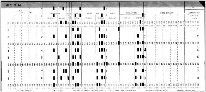
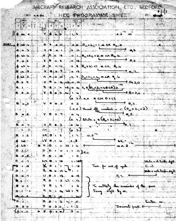
NB The Hollerith punched card offered 80-columns in duodecimal (12 rows). For data and software I/O the card was used in full binary gangpunch mode (up to 960 holes/card), layout described below. An image of a badly worn programming sheet is shown right. With access to such a machine as HEC (the first computer any of us had seen outside an Exhibition) it was impossible to avoid “having a go” and my colleagues and I did write some code beyond a few simple diagnostics. Among the few cards in my possession I have discovered a ‘masterpiece’ written by myself and dated October 1956 which purports to solve a three-order polynomial: [ax3 + bx2 + cx = y]. It might be fun to try but probably embarrassing - would they run on anything functioning today? Computers were rare beasts in the 1950s; sometimes it was possible to share equipment. Multiuser and timesharing were concepts as distant as true real-time computation. By 1957 BTM had sold machines to several companies such as Morgan Crucible and Esso Research and they put us all in touch with each other: a sort of batch mode indirect network. A couple of Esso people would often drive a 300 mile round trip from Fawley in Hampshire and we would meet them yawning over coffee in the morning after a night of stats calculations about whether to build more than one new oil terminal for tankers. What’s in a Name? I understand that I am in disagreement with Raymond Bird (who built HEC1) on the subject of the ‘M’ in HEC2(M). I feel intuitively that the ‘M’ stands for MULTIPLY whereas the man who put the prototype together (and is a few years my senior) insists that the ‘M’ was for ‘marketable’. The one technical fact to back up my contention is that the Vv instruction (which makes true hardware multiply possible) was introduced with HEC2(M). Of course the fact that hardware multiply was on offer might have made the machine much more marketable - - - - - - Vale HEC - Salve Zebra HEC was very reliable and continued to run for nearly three years when, in 1958, it was replaced with a Stantec ZEBRA. HEC was dismantled and transported to nearby RAF Henlow where it continued to run for many years. Card Format (For programming and I/O) On each row of the card column usage as follows:
Note. The OPERAND, NEXT INSTRUCTION and LOCATION fields are divided into 6 bits for the track number and 4 bits for the word within track number. Instruction Set NB - The codes and definitions shown are a ‘best current deduction’.
Jeremy Wellesley-Baldwin is the author of Microprocessors for Industry - Butterworth Scientific (pub). His contact address is jeremy@bournside.plus.com |
A Leo III: 21st Century HindsightDavid HoldsworthIn January 2013 Colin Tully’s collection of printouts of Leo III software emerged from probate; but it would seem that only half of the collection survived. The CLEO compiler was not in the surviving half, but we do have the master routine and the Intercode Translator, and several utility programmes.
When John Daines approached me to ask if our software preservation activity could breathe life back into this back-bone of Leo III’s system, I jumped at the chance, as I had often wanted to work on software for a machine that I never knew, as a way of appreciating what would be involved for future historians to get to grips with machines that pre-dated their own experience. Exploring this software and writing an emulator in order to run it has opened my 21st Century eyes to some computational ideas from the 1960s which now seem to be an intriguing blend of dead ends and spectacular ingenuity. Although much Leo III application software was written in CLEO, Intercode was also an important implementation language for application software, rather quaintly called “Commercial Programmes&rdquo in some of the documentation. I still nurture hopes of finding a copy in an attic somewhere, possibly even on magnetic tape. CLEO was an early block structured high-level language, and old Leo hands talk about it with enthusiasm. We do have the manual which I have yet to explore, but my focus is the preservation of historic software, and without the software my motivation for the study of CLEO is not strong enough to bring it to the top of the pile. It is fascinating to see how this visionary realisation that computers could be just as important for business as for science played out in the early days. Store Architecture Before looking further, we need to see how the words of store are laid out. Actually most of the documentation talks of compartments in the store rather than words, but the most recent updates use the word “word”, as I will do from here on. The store consists of words of 21 bits, a sign digit and 5 quartets, labelled Q1 to Q5 starting at the least significant end. These are actually called short words, and two short words can be combined to form a 41-bit long word. In this case we have 10 quartets and a sign digit. On occasions, this can been seen as a sign digit and 5 octets. The less significant half occupies the lower address; i.e. this is a little-endian machine. The sign bit of the less significant half is ignored. Instructions each occupy one short word, and use the sign digit and Q5 as a 5-bit function code. The next bit (called the discriminant) tells whether we have an instruction operating on a long word or on a short word, and 2 bits are for specifying a modifier register. The remaining 13 bits specify a memory address. There is a way of taking the contents of Q1, 3, 5, 7 and 9 of a long word into a short word, and also setting its sign digit. This has the effect of converting BCD data into quartets with a decimal radix, and is called alpha mode, of which more later. Initial Orders: the challenge At the very summit of the category of spectacular ingenuity, I would put the initial bootstrap. In common with lots of machines that I have met, the initial switch-on reads data into store starting at address 0, and then starts to execute from word 0. This initial code sequence then arranges to read in some more stuff and away we go. Nothing unusual so far, but the Leo III reads 6-bit characters into octets in store so that of the 256 possible contents for an octet, only 64 are possible. It is impossible to set the sign digit, so over half the order code is out of bounds, and the other half is somewhat emasculated. The challenge for the programmer is to write a code sequence to boot up the machine using less than half the order code repertoire. The jump instruction is in the inaccessible half. We have found two versions of this initial code for paper tape each of which is a wonderfully ingenious piece of self-modifying code. These involved using alpha mode access to memory to create proper instructions, place them in memory, where they will get entered without using a jump instruction. A detailed account needs to wait until we have encountered other aspects of the machine, but it is not to be missed (see below). A similar sequence is to be found at the start of the magnetic tape holding the binary code of the master routine. Sign and modulus The data held in memory is in sign-and-modulus form, whether in a short word or a long one. However the arithmetic which all takes place in the 41-bit A register is twos-complement. At least that is the case when the arithmetic is in binary. For other radices it works in groups of 4 digits (quartets) and is complemented using the radix, so an overdraft of £5-19-6d is represented in memory as -05196, but when fetched into the A register it becomes -94006. There is also a 41-bit B register, but data loaded into that retains its sign-and-modulus form. A consequence of sign-and-modulus (also shared with ones complement) is that there are two representations of zero. In Leo III memory we can have -00000 or +00000, and when loaded into A either would give a zero. There is almost a whole page of the Intercode manual (§5) describing how a programmer should deal with minus zero. Initial Orders We have at least three different variants of initial orders for Leo III. One of these is the paper tape start, used for machines which do not have the ability to read the initial orders from mag tape. This tape is read, and it then reads the data from the mag tape as it would have done for a mag tape start. The paper tape start given in the manual Vol IV appendix D is particularly amazing. It trumps the other versions by its sophistication and compactness. It is 32 short words in all. The paper tape would have to be carefully crafted by hand, and so needed to be as compact as possible. The diagnostic log from running this on our Leo III emulator is shown below. The first line (split to fit on the page) is the paper tape as it would look on the machine that punched the paper tape. Below that we show the memory contents as little-endian long words when it is read. In the log the column headed “initial” is the memory content immediately after reading the paper tape. The column headed “code” is the code that actually was obeyed from that location. The contents of the 41-bit A register are shown as before the instruction is obeyed. Chars read = = Q S & L Q K ′ 8 568 4′ 2 H82 Ю6 211
2 4 C2 =8 1 3H82 : 1 5£ H8 1
Long words 68007 20000 - 20006 30000 - 68006 20000
- 5C480 00045 - 46480 00044 - 5C004 2004A etc
address initial code A before execution of instruction
0 ---> 20000 2/0/0 0 || +00000 00000 | TRANSFER (A) TO N
1 ---> 68007 6/1/0 7 || +00000 00000 | SELECT (N)
2 ---> 30000 3/0/0 0 || -FFFFF 37FFB | COPY (A) TO N
3 ---> 20006 2/0/0 6 || -FFFFF 37FFB | TRANSFER (A) TO N
4 ---> 20000 2/0/0 0 || +00000 00000 | TRANSFER (A) TO N
5 ---> 68006 6/1/0 6 || +00000 00000 | SELECT (N)
6 ---> 00045 28/1/0 5 || +5C480 C8005 | BULK COPY ALPHA TO SHORT
7 ---> 5C480 6/1/0 4 || +00000 00000 | SELECT (N)
8 ---> 00044 28/0/0 512 || +80200 20000 | BULK COPY SHORT NUMERIC
9 ---> 46480 24/1/0 522 || +00000 00000 | UNCONDITIONAL JUMP
Long Words, Short Words, Quartets and Octets The packing of information into the words on Leo III is shown below. The bit marked x in the long word is the sign digit of the short word that forms the less significant half of the long word, and is ignored in long word fetches, and set to zero in a long word store.
We can spell out just how the contents of words were shuffled around by looking at the instruction at address 1 in the above example. The action (op code) 6 is SELECT which is Leo speak for fetch. It has a discriminant of 1 to indicate a long word, and the address is odd to indicate the magic alpha mode in which the long word is shuffled into a short one. The long word that occupies addresses 7 and 6 contains 5C480 00045. Leo is little-endian so the bottom half (0045) is in word 6. In this alpha fetch Q1, Q3 and Q5 come from word 6, and Q7 and Q9 come from word 7 and deliver C8005, but the 5 at the start of word 7 indicates that this value is negative, so we see it in A after conversion to 2s complement. However, when it is stored in word 6 by the instruction at address 3, it is converted back to sign-and-modulus. We see it back again when it is fetched at address 5, but this long word fetch ignores the spare sign digit, so we see the C8005 in the least-significant half of A. What about the apparently useless instructions in words 0 and 2? This is explained by looking at the way that the paper tape characters are mapped onto octets. Alpha characters in the store are held as a control quartet and basic quartet according to the table below. The value of the control quartet cannot exceed 7.
                             Basic Quartet
                  0  1  2  3  4  5  6  7  8  9 10 11 12 13 14 15
                _________________________________________________
             0 |  Sp                                             |
             1 |  -                                              |
             2 |  &                                              |
     Control 3 |  0                                              |
     Quartet 4 |     1  2  3  4  5  6  7  8  9  10 11  +  :  . £ |
             5 |     A  B  C  D  E  F  G  H  I  =  *  ′  ?  ≡  □ |
             6 |     J  K  L  M  N  O  P  Q  R  →  %  >  <  ½  \ |
             7 |     /  S  T  U  V  W  X  Y  Z  (  )  ,  ;  Ⅲ Δ |
               |_________________________________________________|
? = ‘Doubtful Block’ mark \ = Alignment Mark Ⅲ = Block End ≡ = Line End ; = Number End Δ = Erase There are only 64 octets that can be read from paper tape (or mag tape for that matter), including Ⅳ (Block End) which occurs only as the last character of every transfer. However, the way that the middle octet is split across 2 short words, means that the restrictions on what can be read into each of the two halves are different. If they had tried to omit those useless instructions, word 0 would have been 68007 and word 1 20006, giving us a long word of 20 00 66 80 07 when expressed as 5 octets. So the 5 paper tape characters would need to be &_Oxx, where underline represents space and the two lower case ‘x’s indicate that neither 80 nor 07 could be read from paper tape. I can only imagine the difficulty of devising this code using only pencil and paper. Variable Radix The radix used for arithmetic is held as 5 quartets in the C register. When doing arithmetic the radix for Q1 to Q4 of A is taken from Q1 to Q4 of C, and for Q5 to Q10 it is taken from Q5 of C. Sterling arithmetic (UK money until 1971) used a radix of 10 10 2 10 12, which is represented in C by the “excess constants”, i.e. the number that you need to add to make it carry, i.e. 6 6 14 6 and 4. So when a penny is added to £23-19-11, 2 3 1 9 11 first becomes 2 3 1 9 12. When the excess constants are added we get 8 10 0 0 0, and we then have to take the excess constant away again if there was no carry, so we get 2 4 0 0 0. Tenpence and Elevenpence We have some difficulty representing the digits that exceed 9 and so did Leo. So as to enable printing of sterling money, the printers had characters for 10 and 11 squashed into a single character space. From our copy typing of print out it can be seen that this was not always easy to decipher. Perhaps the prices in Lyon’s tea shops were always multiples of threepence in order to avoid encountering this problem. Digits 12 to 15 used the next characters in the table, viz. + : . £. In 2001 some Leo III paper tapes were given to CCS, and we have discovered that they contained a program to print out conversion tables for this arrangement, but we should be thankful to IBM for popularising hexadecimal. I have not mentioned halfpennies, but Leo III could print them too. Instruction Mnemonics There weren’t any. Instructions had long names which basically said what they did such as PREPARE FOR DIGIT COLLATION, and they also had numeric values between 0 and 31. Veteran Leo III programmers have these numbers indelibly written into their brains. Object Programs in Memory Like the IBM 360, the Leo III was a real memory machine. There was no translation between the address of a memory location as seen by the program and the actual store, which consisted of up to four divisions each of 8192 short words. An instruction could address directly any location in the division in which it was itself located. A program was divided into chapters. No chapter could span across a division boundary. A binary program on magnetic tape had two words for each instruction, the instruction itself, and a parameter number to indicate which of a vector of parameters was to be added in. The parameters were decided at load time, and most of them were the addresses where the chapters were to be placed in memory. Each chapter had a procedure 0 at its start, and this held all the parameter values and so gave access to other chapters. A modify instruction rather like the ICT 1900’s SMO (Supplementary Modifier) instruction allowed the contents of any location to be used to modify the address of the next instruction. When a program was loaded into memory, the parameter values were added in to make hardware instructions. Overlapping of I/O and CPU activity was built into the system architecture with a subtle double buffering scheme. The address for transfer of data on device on route R was held in word 64 + R, and a pseudo-route P was allocated to point at the other buffer via word 64 + P. The actual route which a program was to use was only known at run time, so the parameter mechanism was used to deal with this and procedure 0 held a parameter which had the pseudo-route number, and another one holding -(64+R). The magic modification order had a variant which would follow a chain until it got to a positive value, so data in a buffer could be accessed starting with a file number known to the programmer, which then pointed to a parameter, which held -(64+R) which then led to the data in the buffer. There was even a special instruction for swapping route and pseudo-route pointers. So the chapters of an object program could be scattered in memory, each starting with its copy of procedure 0 which told it where everything else could be found. Intercode Systems software was written in Intercode. This is a sort of machine code for a fictitious machine rather like the Leo III, but with less restrictions on many instructions, and facilities for driving files on magnetic tape, printer, card reader, and even a gadget for reading cheques. The source code is almost entirely numeric. There are a few key words like PROCR, CONST, TABLE. (Remember five characters fit into a long word.) Each instruction consisted of six fields, an action, a reference, an item, a discriminant, a modifier and a literal. Its location was indicated by a serial number, which unlike BASIC went up in steps of 1, and was akin to a memory address in this fictitious machine. Here is Hello World! , as it would look on the machine that punched the paper tape: PROGM;123;1;1;HELLO WORLD
ENTRY;100;3;RS;KSK
CHAPS;1;100
SHEET;1
PROCR;100;LOG OUTPUT
0;154;200;;;;;OUTPUT TO LOG
1;151;;;;;;UNLOAD PROG
SHEET;2
CONST;200;1
0;(A)HELLO
2; WORL
4;(A)D (D)5.5.;2 LINE ENDS
END
When it is translated by the Intercode Translator (known to Leo veterans as 08000), the printout looks like: PROGM 123 1 0 HELLO WORLD
ENTRY 100 3 RS KSK
CHAPS 1 100
INDEX 2 1
10000 PROCR 100 100 LOG OUTPUT
10002 154 101 2 0 0 0 200 OUTPUT TO LOG
10003 151 0 0 0 0 UNLOAD PROG
10100 CONST 101 200 1
10102 (A)HELLO;
10104 WORL;
10106 (A)D (D)5.5.; 2 LINE ENDS
10200 END
The serial numbers have been modified, as has the number of the constant section. The only non-numeric naming that the programmer can choose is the name of each file, which consists of a single letter and a single digit. And the name on the listing is the same as the programmer chose. It is impressive how many of the built-in words have 5 letters and so fit in a long word. After a while one can come to like PROCR and PROGM. Not only are all the instruction op codes (known as actions in Leo speak) numbers, but there are over 100 of them to remember in Intercode. Not only are the routine numbers modified so that they are contiguous, but the AMEND facility that is an integral part of the Intercode system allows you to edit the code, which necessarily involves sliding the serial numbers up or down as instructions are added or removed. Intercode is a machine code rather than an assembly language, but it sits within a processing system that allows you to edit the code with less pain than might have been the case. The repeated renumbering means that the programmer must rely on comments for finding familiar parts of the code. Actually there are both comments and notes. I have yet to comprehend the difference, but Leo veterans seem to understand it, and are baffled by my non-comprehension. As a further aid to following the code, the Translator labelled the destination of each jump instruction (except subroutine entry) with the serial number(s) of the jump instruction(s) that went there. Variable Radix Again Constants in Intercode can be of five different types:
A line of program code represents an Intercode instruction and has the following fields:
A reference can be to a file, in which case it is a letter followed by a digit. An item sometimes is a serial number, and sometimes an actual count of hardware locations from the start of the procedure or section. These are often the same, but not always, and then it depends on the type of action as to which meaning is used. One Instruction Mnemonic for Intercode There weren’t any mnemonics in Intercode, at least not deliberately, I’m sure. However, we discovered occasional occurrences of an action code of GO rather than a number, and the Intercode Translator was clearly happy with this. This turned out to be a bit of ingenuity that must have been serendipity. It was obvious that the instruction needed in these cases was an unconditional jump, which in Intercode was 76. The characters 76 were represented by the two octets 47 46. If an alpha mode fetch is used to read this into the A register in order to get the binary value 76, that would have the same effect as reading 57 66 (the representation of GO) which would also give the binary value 76. Not all substitution of letters for digits work in this way, but many do, e.g. a 34 instruction can be achieved by CD. We have seen no other example of such accidental mnemonics. Implementation of the Intercode Translator The Intercode Translator is written in Intercode. This must be an early example of a language processor written in its own language. It would be good to know just what ingenuity was used in this task. Rescuing the Translator from a printer listing involved getting a binary program. The printout from an Intercode translation optionally ended with a listing of the machine code generated. The listing that came to us had been torn off at this point, perhaps by an ardent advocate of paper recycling. So our software rescue involved writing both an emulator of the Leo III hardware, and also a new Intercode translator. Needless to say the language of choice for this 21st century version was not Intercode. EDIT etc The Leo III machine code orders for editing data do what most computers can only do in subroutines, but then Leo III was a microcoded machine, but the microcode was hard-wired. Multi-programming and re-entrant code The Leo III veterans are keen to claim that it was the first machine to have multi-programming, called time-sharing in those days. Whatever the truth of these claims, it was certainly a very early multi-programming system, and as a real memory machine would have been able to deploy re-entrant code, except that the subroutine entry instruction planted the return address immediately ahead of the entry point to the subroutine, thus making read-only code very difficult to write. 20/20 Hindsight This has been a fascinating glimpse into the mindset of programming in the 1960s. It must have required great patience and much desk checking in an environment where turn-round was often overnight. My own 1960s computing was on the English Electric KDF9 where the assembly language (Usercode) had numbered routines and numbers for labels. This seemed odd because an earlier KDF9 assembly language had had mnemonic labels. Looking back, I wonder, was Usercode an ill-conceived child of the merger of English Electric and Leo? Perhaps the quirks of Intercode were a natural spur to the development of CLEO. Maybe some of the quirks are there because Intercode was considered more important as the target language for the CLEO compiler, rather than a programming language in its own right. You are likely to find your way to executable Leo III code by clicking: sw-pres.computerconservationsociety.org/leo.. Acknowledgements This 21st century appreciation of Leo III has only been possible because of the dedicated efforts of several Leo III veterans, and the goodwill of the Leo Society. John Daines, Ray Smith, Geoff Cooper and Ken Kemp have stuck with the enterprise and continue to do so. Valuable work continues in improving our on-line documentation. Chuck Knowles, Tony Jackson and Dave Jones also made invaluable contributions to the laborious and painstaking process of copy-typing the surviving line-printer listings. Helpful nuggets of information have been provided from time by other members of the Leo Society. David Holdsworth is a leading member of the Computer Conservation Society with particular responsibility for software conservation and for emulation. He believes that software is only properly conserved if you can run it. David can be contacted at david.holdsworth@bcs.org. |
||||||||||||||||||||||||||||||||||||||||||||||||||||||||||||||||||||||||||||||||||||||||||||||||||||||||||||||||||||||||||||||||||||||||||||||||||||
Retro Computing with a Difference
Michael Brisk
Shakespeare famously wrote “Crabbed age and youth cannot live together”. Shakespeare displayed a wide knowledge of human emotions and behaviour, but he knew nothing of technology, nor could he have known of computers. In this article I describe how a “marriage” of a fifty-year old technology – a transistorised analogue computer from 1963 – with a digital microcontroller from 2013, can indeed achieve a harmonious union, with the two living very well together. This fits the category of “retro computing”, but differs in that most enthusiasts tend to focus on digital computer heritage. So let’s talk about analogue computers. But are they not obsolete – the dinosaurs of computing? Indeed, electronic analogue computers, developed to replace earlier mechanical differential analysers, first appeared in the very late 1930s and early 1940s. They reached their peak use in the 50s and 60s, notably, but not exclusively, in aeronautical design, and then were superseded by digital machines with appropriate simulation software in the 1970s. Today they exist virtually only as exhibits in museums of technology and are largely overlooked by those interested in computing history, as their interests tend to centre on digital machines. Yet in their day, analogue computers were highly regarded, valuable tools to solve engineering problems which can be described by differential equations: dynamic problems of all types, and in particular, from my personal perspective, all aspects of process dynamics and control. Incredible as it may sound to those familiar with modern digital computers, analogue computers, inherently parallel machines, were many orders of magnitude faster in solving dynamic problems than digital computers of the day. An outstanding example was the use of large (over 400 amplifier) analogue computers in the US in the 50s to solve missile flight equations. The analogue solution took typically one minute. A digital “check” solution by numerical methods on an early IBM took 75 hours! I first encountered analogue computers as a final year undergraduate student in Chemical Engineering at the University of Sydney in 1959. A recently arrived academic had purchased two Systron-Donner, ten operational amplifier, 100V vacuum tube machines. He offered an elective course in dynamic simulation to complement his newly introduced course in process control. Four years later, in 1963, as a very junior lecturer teaching introductory process dynamics and control, I persuaded the Department to upgrade the Donner computers to the then brand new Electronic Associate Inc. (EAI) TR-20 10V transistorised analogue computer at the significant cost of about $A10,000. EAI, headquartered in New Jersey, was a major developer and supplier of electronic analogue computing equipment in the 1950s and 60s.
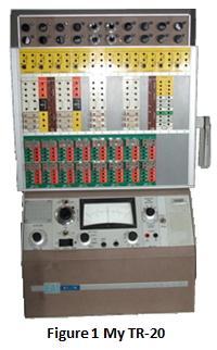
The TR-20, also known as the PACE (Precision Analogue Computing Equipment) TR-20, was a 20-amplifier machine. It incorporated non-linear solid-state computing components, including quarter-square multipliers and general purpose diode function generators. It had excellent high speed repetitive operation capability, removable patch panels, and – bliss – it had almost no drift, and was surprisingly robust to student mishandling. With this tool for illustrating process dynamics and control system behaviour in the classroom and laboratory I thought all my Christmases had come at once! In 1965 we were able to upgrade the laboratory to an EAI TR-48 desktop analogue computer, a much more powerful machine with some hybrid digital logic capability. However, at about this time simulation languages, which in effect mimicked an analogue computer on a digital computer, started to appear. I introduced IBM’s CSMP (Continuous System Modelling Program) on the Department’s IBM 1620, and the use of the analogue computers gradually died, although the TR-20 remained a useful lecture demonstration tool. Amusingly, EAI’s marketing literature described it as “portable” (presumably compared to the desktop TR-48). But at 50kg, it was only portable on a trolley! My last professional use of an analogue computer for control system studies was in 1966-67 whilst working at ICI’s Central Instrument Research Laboratory, Pangbourne, UK. ICI boasted a very large Solartron machine. From then on, digital computer simulation systems became my tools, both for industry applications and academic teaching, although I confess to occasionally having yearned for the flexibility and “intimacy” achieved when interacting with an analogue. So you can perhaps understand my surprise and nostalgic pleasure when, during an engineering accreditation visit to the University of Technology, Sydney (UTS) in 2013, I was shown an EAI TR-20 computer in the Electrical Engineering School. The machine was covered in dust, apparently having been stored without use for about 20 years. The School was in the process of moving into new buildings, and the computer was to be discarded. I quickly volunteered to take it, and, after some bureaucratic negotiations and paperwork, I received it, together with an assortment of spare parts and two spare patch panels. I now have a 1963 TR-20 at home (Figure 1 above). It has 16 amplifiers, eight integrator networks, two multipliers, a variable diode function generator and an electronic comparator; close to a fully expanded machine. It has an interesting history, having been purchased new in 1964 by the then newly-created New South Wales Institute of Technology (previously Sydney Technical College). One of the patch panels still has NSWIT asset register number 67 attached to it. The College in turn became UTS in 1988. No-one at UTS seems to have had much interest in using the machine, which possibly explains the amazing fact that it is still in almost full working order.
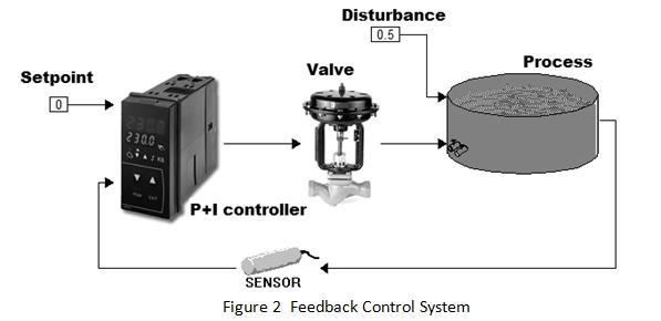
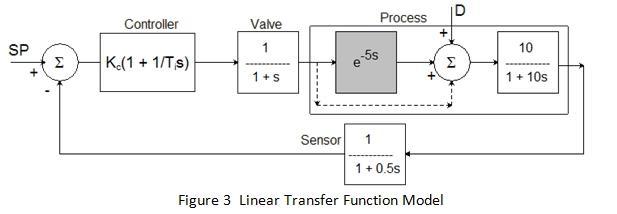
This article is not intended as a tutorial in analogue computers, but a brief explanation of how they were used for control system simulation and design may be useful as background for the new development we will discuss shortly. Figure 2 shows a simple feedback control system one could use in a classroom to illustrate concepts. The task here might be temperature control of the tank contents in the face of some inlet disturbance, using a proportional plus integral (P+I) controller. Arbitrary units of change are used, hence the zero setpoint. Figure 3 presents a simple linear transfer function model for the control loop.
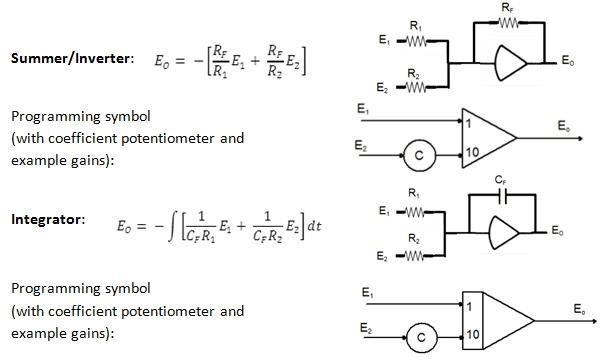
The “process” has been represented by a first-order plus dead time model which could apply to a tank with imperfect mixing, for example. The disturbance is assumed to enter downstream of the dead time. From an analogue computer perspective, the dead time poses a problem. It could not be simulated in the analogue machines of the 1960s, and would have had to be approximated in various ways that need not concern us here. For the present we will ignore it, and treat the path from valve to process as following the dotted line. We can “solve” the transfer function model on the analogue computer, for various values of the controller gain, Kc and integral time Ti, by wiring up a circuit which has the same dynamic (differential) equations as the model. The linear computing components on an analogue computer are high gain DC operational amplifiers and linear potentiometers. The amplifiers can be used as inverters and summers with resistance feedback; or integrators with capacitance feedback. The latter case permits the solution of differential equations. The basic linear “programming components” available are:
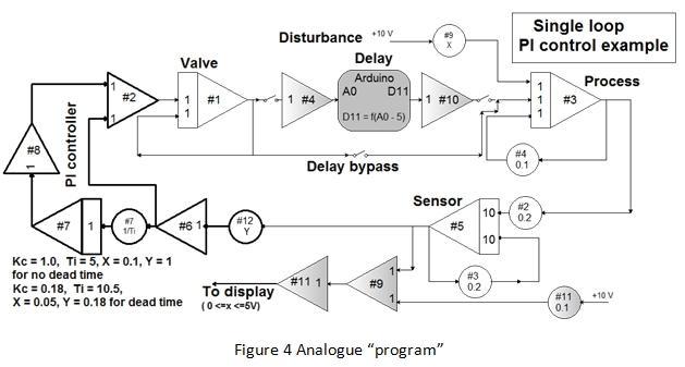
RF is typically 100kΩ, with the input resistors, R1 and R2, either 100kΩ or 10kΩ, leading to gains of 1 or 10. Accurate (typically 10-turn) coefficient potentiometers (0≤C≤1) in series with the input resistors are used to achieve other multiplying factors. The integrator feedback capacitor is typically 10µF. The basic integration time constant (RC) is thus one second. Using these symbols, and applying well-defined programming procedures, available in any analogue computer handbook, to the equations from the block diagram of Figure 3 leads to the circuit shown in Figure 4 (excluding the shaded Arduino block and inverters #4 and #10 which we will ignore for the moment). The summer #9 and inverter #11 scale the response signal for display purposes as my equipment can only handle positive signals to 5V.
The computer “solves” the equations because the circuit developed has the same differential equations as the problem in the block diagram. It is then a simple matter to carry out a series of runs, adjusting the controller tuning to achieve a desired response quality. I aimed for a decay ratio (height of second peak to first peak) of 0.25, leading to the parameters shown in Figure 4.
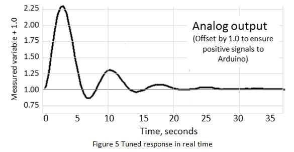
Figure 5 shows the response achieved for the case without dead time. In the absence of a plotter, I use the analogue-to-digital capability of an Arduino Uno R3 microcontroller to transmit the signals to plotting software on a PC. Figure 5 is a screen capture from the PC. As the Arduino can only handle signals in the range 0 to 5V, the 1V offset is required (provided by amplifier #9 and potentiometer #11 shown in Figure 4). The achieved decay ratio was 0.23. The time scale is real seconds. Of course, the actual “process” could have a very different time scale. The real time constants could be hours. The fact that the solution can be obtained in seconds on the analogue computer as it solves all the equations in parallel, makes it a very powerful tool. The question is, how accurate is the result? To test this I ran the identical simulation on a modern digital dynamic simulation package, VisSimTM by Visual Solutions Inc. The differential equations were integrated using an adaptive Runge Kutta 5th order algorithm to ensure good accuracy. I have not shown a comparison plot for the simple reason that the two response curves overlay each other exactly within the width of the traces. Not bad for 50-year old electronics! Once the analogue “program” was established, the two desired tuning parameters were obtained in a succession of trial-and-error runs taking only a few minutes in total. However, in more complex problems a combination of many parameters may be required to find an optimum solution. Repeated trial-and-error with multiple parameter adjustments will be time consuming. The real power of the electronic analogue computer then comes to the fore: its ability for high-speed repetitive operation (rep-op). The speed of the problem solution can be greatly increased by increasing all the integrator gains by the same amount. If all the feedback capacitors are reduced from, for example, 10µF to 0.02µF the speed increases by a factor of 500. A solution that took 35 seconds can be achieved in 70 milliseconds. The TR-20 has high speed rep-op with compute times ranging from 20 to 500 milliseconds. The machine cycles automatically between “reset” and “operate” using high speed relay switching, with the reset duration fixed at 10 milliseconds. The output response can be displayed on an oscilloscope, and its shape will appear to change continuously in response to gradual parameter changes as coefficient potentiometers are adjusted.
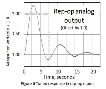
Figure 6 shows a screen capture, adjusted to the same scale as the previous graph, of the response to the tuned, controlled system without dead time under rep-op with a 200 millisecond compute time. (In the absence of a hardware oscilloscope, I display the signal on a PC screen using a FOSC USB PC oscilloscope and related software.) The response is slightly more noisy, but otherwise agrees with the real-time solution. These examples demonstrate the power that analogue computers provided for teaching process control, as well as their value to industry practitioners when it was possible to provide realistic dynamic models. Unfortunately, in the process industries those models frequently incorporate a dead time component. This may be a real dead time arising from a transport delay such as a pipeline, or a “virtual” dead time used to model a high order process. Analogue computers could not simulate dead time. Digital computers of course can do so, and various hybrid facilities were introduced in the late 60s and 70s, but they were very costly, and rapidly ceased to be competitive with full digital simulation packages as the power and speed of digital computers increased. Today digital computation reigns supreme for dynamic simulation. But with a genuine analogue computer at my disposal, I wondered why I could not “marry” it with a modern digital device. And what better device to use than the very low cost, open-source microcontroller board based on readily understandable hardware and software, the Arduino Uno. The device includes six 0 to 5V analogue inputs, and six pulse width modulation (PWM) outputs which can be adapted for 0 to 5V analogue output. It can be powered via a USB connection to a PC, and is very simple to program in what is essentially the C++ language.
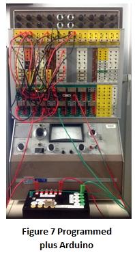
I use a simple “pipe-line” array, or “shift register” delay algorithm in the Arduino. The Arduino program is shown in the Appendix, minus the variable declarations so as to save space. The pipe is divided into 10T 0.1 second elements for a dead time of T seconds. Every 100 milliseconds the software shifts all values forward, replaces the inlet element by the voltage value read from the analogue computer, and sends the element that has exited the end of the pipe back to the analogue. The 490Hz PWM output signal is fed through a low pass filter (here with a time constant of 22 milliseconds). Inverter #4 in Figure 4 ensures the Arduino receives a positive voltage, and inverter #10 provides the necessary negative input to the process integrator #3. Figure 7 shows the TR-20 programmed as in Figure 4 to model the complete block diagram of Figure 3 including the dead time. The Arduino is mounted in a small box provided with the necessary patching terminals. The Arduino code also enables the measured variable to be plotted on the PC which is also providing power via a USB connection.
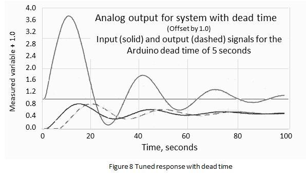
Figure 8 shows the analogue response for the tuning parameters of Figure 4, offset by 1V as before. It also shows the analogue signals from the valve (amplifier #1, inverted through #4 into the Arduino in solid line), and the signal leaving the Arduino in dashed line. Note the delay of five seconds between them. How accurate is this result? A comparison with a simulation in VisSimTM, which has a digital dead time module, again produced indistinguishable curves. These results have been obtained in real time mode. Ideally one would wish to run the analogue in rep-op to tune the controller rapidly. Unfortunately, the available memory of the Arduino prevents this. Dividing the sample interval of 100ms by 500 would require a very long “pipe-line” array: 50kB for a five second delay. The Arduino Uno has 2kB of RAM for data storage. The relatively low frequency of the PWM output would also be an issue. No doubt larger, faster microprocessors with true digital-to-analogue output could be used, but would defeat my objective of enhancing the vintage machine in a simple, but very modern way. Shakespeare went on to write “youth is nimble, age is lame”. In fact we have an example here of almost the reverse. The old analogue computer, by virtue of its parallel computing capability, and scope for small integrator time constants, can indeed be very nimble for dynamic problems. The Arduino cannot match this, although no-one would describe it as “lame” in an appropriate application environment. Married to the analogue for real-time solutions it performs very well. But the most satisfying outcome for me was to see a true vintage analogue computer, after 50 years, still able to perform to its specifications. The old saying “they don’t make them like they used to” seems very apt here. Appendix. Arduino code (excerpt) void setup() {
for(ii = 0; ii < 200; ii++) { // max dead time is 20sec
// with 0.1 sec sample intervals
pipelineArray[ii] = 0.0; } //zero the pipeline initially
deadTime = 5.0; // for demonstration purposes
N = int(deadTime * 10); // number of 0.1 sec intervals to be used
}
void loop(){
for(kk = N-1; kk > 0; kk = kk - 1){
pipelineArray[kk] = pipelineArray[kk-1];
} // shift the values through the dead time pipe
timeNow = millis(); // time since start in milliseconds
analogInteger = analogRead(inChannel); //read the I/P voltage as an
// integer in range 0 - 1023
pipelineArray[0] = analogVoltage; // accept new input value
delayedOutput = float(pipelineArray[N-1]*5.0/1023.0);
// set new return value to computer
PWMout = int(255*(delayedOutput/5.0)); // compute output signal to computer
if(PWMout > 255){ PWMout = 255; } // do not exceed output limit
analogWrite(PWMpinOut,PWMout); //send signal to computer
while((millis() - timeNow) <= 100){ } // wait for 0.1sec, the sample interval
}
Emeritus Professor Michael Brisk is a retired chemical engineer. He spent about half his professional life in process control with ICI in the UK and Australia, becoming International Technology Leader Advanced Process Control, and half as an academic at the University of Sydney, and later at Monash University, Melbourne where he was Dean of Engineering. He can be contacted at mbrisk@bigpond.net.au . |
40 Years ago .... From the Pages of Computer WeeklyBrian AldousUS forces consider Coral 66: The policy of the US armed forces on the development of real time computer languages is in the course of a dramatic re-assessment, with the aim of standardising on one language for all defence applications. One of the candidates to be considered for this position is the UK standard language, Coral 66. (CW 448 p11) ICL’s top-down policy backfires: A harsh blow to ICL’s ‘top-down’ approach in introducing its 2900 series has come in the shape of a £750,000 contract awarded to Honeywell by National Freight Corp. for a 192K 66/20 which will replace two ICL 1900 machines. (CW 449 p1) Challenge to Intel from AMI: A determined challenge to Intel’s dominance of the microprocessor market with its 8080 has been launched by AMI Microsystems with its Motorola MC6800 based S6800 chip. (CW 449 p7) Massive orders lined up for 2900: Massive investments in ICL 2900 systems are being considered by ICL’s two largest commercial customers, Hawker Siddeley Aviation and Plessey. Each has about £6m worth of equipment on rental. (CW 450 p1) Versatile micro from Intel: Process control, traffic control and point-of-sale processing are just some of the wide range of applications areas seen by Intel for its single PC board microcomputer module, the 4-43, based on the Intel 4040 4-bit processor. (CW 451 p7) Molecular range boosted on BC(S)L’s birthday: First birthday celebrations at the Brighton offices of Business Computers (Systems) Ltd last week coincided neatly with the company’s announcement of what it claims to be the lowest-cost disc-based configuration in the world, the Molecular 3M(E), and the largest member of its family, the Molecular 18M(E). (CW 454 p3) British Steel contracts for GEC: The rolling of high quality stainless steel is to be controlled by GEC 4080 computers at the British Steel Corporations’ Special Steels Division Stainless Works at Sheffield. (CW 454 p28) Xerox pulls out after six years of losses: Six years after its entry into the computer business, in the course of which its computer operations have steadily lost money, Xerox Corp. has decided to pull out of the manufacture of mainframes, writing off some £38m in the process. (CW 455 p1) BBC to get 2960 for bureau use: On the lookout for a replacement for its London-based ICL 1904S, the British Broadcasting Corporation has sent a letter of intent to ICL regarding a 2960, the machine which is not expected to be officially announced until October. (CW 455 p1) The end for exchangeable disc storage?: Heralding what could be the beginning of the end for exchangeable disc storage at big installations, IBM has announced the 3350 and 3344 fixed disc drives, compatible with the 3330 and 3340 respectively, but with up to four times the capacity. Meanwhile, CDC now offers a compatible high capacity drive, the 9766, as an OEM product to IBM’s mainframe competitors. (CW 455 p32) Post Office order for three 2970 machines: One of the biggest but least surprising contracts for ICL 2900 series computers has been placed by the Post Office, which has ordered three 2970s worth £6 million to replace ageing Leo 326 machines at its Edinburgh and Derby telephone billing centres. (CW 456 p48) First two customer 2970s go in: The first two customer ICL 2970s have been delivered. One has gone to Edinburgh Regional Computing Organisation, to provide a service for the universities of Edinburgh, Glasgow and Strathclyde. The other has been installed at the Swindon HQ of W.H. Smith, the newsagents. (CW 457 p1) Centronics to open head office in Britain: With something like 4,000 of its printers now installed in the UK, Centronics is setting up a direct selling operation here and intends to open a UK head office at Cheam, Surrey. (CW 457 p3) Domestic teletext by phone project: Viewdata is the name given to a research project currently under way at the Post Office. The idea behind it is that the telephone might be used to supply a visual text service in the home similar to the BBC and IBA’s experimental teletext services, which use blanking lines in the television signal to carry data which can be displayed on a normal television set with the addition of a decoder. (CW 457 p32) Coral 66 compiler for Mk 2 Nimrod: A cross-compiler likely to be used in the development of software for the Mark 2 Nimrod marine reconnaissance aircraft will be developed by CAP, under a contract from Marconi-Elliott Avionic Systems. The Coral 66 compiler will generate object code for Marconi’s 920 Advanced Technology Computer. (CW 459 p9) Packet switching service takes step forward: Preparations for the introduction of the Post Office’s Experimental Packet-Switched Service have taken another step forward with the interchange of packets between the Post Office in London, using an Interdata 50 mini, and ICL at Letchworth where a 7503 RJE terminal was linked to a 1903A. Transmissions were at 2,400 baud, up to the level of packet interchange, indicating compatibility between two independently designed terminals. (CW 460 p3) |
Forthcoming EventsLondon Seminar Programme
London meetings normally take place in the Fellows’ Library of the Science Museum, starting at 14:30. The entrance is in Exhibition Road, next to the exit from the tunnel from South Kensington Station, on the left as you come up the steps. For queries about London meetings please contact Kevin Murrell at kevin.murrell@tnmoc.org or by post to 25 Comet Close, Ash Vale, Aldershot, Hants GU12 5SG. Manchester Seminar Programme
North West Group meetings take place in the Conference Centre at MSI – the Museum of Science and Industry in Manchester – usually starting at 17:30; tea is served from 17:00. For queries about Manchester meetings please contact Gordon Adshead at gordon@adshead.com. Details are subject to change. Members wishing to attend any meeting are advised to check the events page on the Society website at www.computerconservationsociety.org/lecture.htm. Details are also published in the events calendar at www.bcs.org.
MuseumsMSI : Demonstrations of the replica Small-Scale Experimental Machine at the Museum of Science and Industry in Manchester are run every Tuesday, Wednesday, Thursday and Sunday between 12:00 and 14:00. Admission is free. See www.mosi.org.uk for more details Bletchley Park : daily. Exhibition of wartime code-breaking equipment and procedures, including the replica Bombe, plus tours of the wartime buildings. Go to www.bletchleypark.org.uk to check details of times, admission charges and special events. The National Museum of Computing : Thursday, Saturday and Sunday from 13:00. Situated within Bletchley Park, the Museum covers the development of computing from the wartime Tunny machine and replica Colossus computer to the present day and from ICL mainframes to hand-held computers. Note that there is a separate admission charge to TNMoC which is either standalone or can be combined with the charge for Bletchley Park. See www.tnmoc.org for more details. Science Museum :. There is an excellent display of computing and mathematics machines on the second floor. The new Information Age gallery explores “Six Networks which Changed the World” and includes a CDC 6600 computer and its Russian equivalent, the BESM-6 as well as Pilot ACE, arguably the world’s third oldest surviving computer. Other galleries include displays of ICT card-sorters and Cray supercomputers. Admission is free. See www.sciencemuseum.org.uk for more details. Other Museums : At www.computerconservationsociety.org/museums.htm can be found brief descriptions of various UK computing museums which may be of interest to members. |
CCS Web Site InformationThe Society has its own Web site, which is located at www.computerconservationsociety.org. It contains news items, details of forthcoming events, and also electronic copies of all past issues of Resurrection, in both HTML and PDF formats, which can be downloaded for printing. We also have an FTP site at www.cs.man.ac.uk/CCS/Archive, where there is other material for downloading including simulators for historic machines. Please note that the latter URL is case-sensitive. |
Committee of the Society
|
Computer Conservation SocietyAims and objectivesThe Computer Conservation Society (CCS) is a co-operative venture between BCS, The Chartered Institute for IT; the Science Museum of London; and the Museum of Science and Industry (MSI) in Manchester. The CCS was constituted in September 1989 as a Specialist Group of the British Computer Society (BCS). It thus is covered by the Royal Charter and charitable status of BCS. The aims of the CCS are to
Membership is open to anyone interested in computer conservation and the history of computing. The CCS is funded and supported by voluntary subscriptions from members, a grant from BCS, fees from corporate membership, donations, and by the free use of the facilities of our founding museums. Some charges may be made for publications and attendance at seminars and conferences. There are a number of active Projects on specific computer restorations and early computer technologies and software. Younger people are especially encouraged to take part in order to achieve skills transfer. The CCS also enjoys a close relationship with the National Museum of Computing.
|
