| Resurrection Home | Previous issue | Next issue | View Original Cover | PDF Version |
Computer
RESURRECTION
The Bulletin of the Computer Conservation Society
ISSN 0958-7403
Number 59 |
Autumn 2012 |
| Editorial | Dik Leatherdale |
| Society Activity | |
| News Round-Up | |
| Atlas 50th Anniversary | Simon Lavington |
| Enigma Challenge 12-17th June 2012 | John Harper |
| More Misplaced Ingenuity | Hamish Carmichael |
| Memories of Maximop Development | Arthur Dransfield |
| The Sacking of Tommy Flowers | Jork Andrews |
| Forthcoming Events | |
| Committee of the Society | |
| Aims and Objectives |
On page 29 we reprint an article about the late career of Tommy Flowers, known to us as the creator of Colossus. The article originally appeared in a newsletter for BT Research Establishment retirees and appears by kind permission of its editor. Some of the technology referred to may be foreign to CCS members and references to earlier articles are of course to the BT newsletter, but rather than try to adapt it to the CCS context we thought it best to present it as originally published rather than risk the introduction of errors and distortions. It fills a gap in my understanding of the story — perhaps yours too.
Readers will have noticed that Resurrection 58 arrived in a plastic wrapper rather than the usual envelope. As part of our drive to keep costs under control and to avoid undue distribution delays, the BCS has engaged a new printer who is willing to undertake distribution as well as printing. This seems to be working well so far albeit not without some teething troubles.
To further streamline the process, this edition of Resurrection has been originated as an A5-sized document rather than being produced in A4 and being reduced in size during the printing process. There will be some minor changes in format, but nothing too drastic, one hopes. One unavoidable change is that the .pdf edition on the web will henceforth be in A5. On the screen, Adobe Acrobat seems to take care of that, but if you want to print it as an A5 booklet, you will have to use the Fit to Printable area option in the print dialogue.
North West Group contact detailsChairman Tom Hinchliffe: Tel: 01663 765040. |
Elliott 803
Over the last few months on Saturday mornings Peter Onion has given a series of lectures about the 803 to TNMoC volunteers. How it Works: The 803 covered the 803’s architecture and the logic circuits it uses. How to Work the 803 covered operating the 803 in sufficient detail for volunteers to be able to turn the machine on and run simple demonstration programmes.
Some engineering work has been required to keep the paper tape reader operating correctly. This was partly caused by preventative maintenance (i.e. cleaning the optical lens) leaving a spot of grease behind. This was just enough to reduce the light level on one channel to the point that it started to misread tapes.
Also the minilog gate in the paper tape station that drives the READY line failed. According to our ex-Elliott field service engineer John Sinclair “they do that sometimes”. A previously unused part was used to replace the faulty unit. At 50ish years old calling it a “new part” would hardly be accurate!
A survey of TNMoC’s stock of spare 803 logic boards revealed that all the boards needed to install option SB103 in the 803 are available. SB103 provides 13 bits of parallel input and output to/from the 803’s accumulator. Work has begun to thoroughly test all the boards (which include two nickel delay lines) before they are installed in the machine. Ideas are being sought for peripherals that can be built and connected via this “new” facility that will relate to the 803s use in process control and automation systems.
Elliott 903
In April, a fault developed on the 903’s extra store. The fault was located by card swapping store cards with the scrap 903. The faulty card was an A-EA3, store inhibit drivers and sense amplifiers, which has been temporarily replaced by a spare. The suspect card worked in my own ARCH 9000, suggesting that the fault was simply an unbalanced sense amplifier. The potentiometers which are provided to balance these amplifiers were duly adjusted, but to no effect. The card still worked on my ARCH 9000 but still failed on the TNMoC 903.
Otherwise the 903, which arrived at TNMoC in November 2010, now appears to have entered a phase of relative reliability notably over the very hot weather earlier when the poor old 803 had to have a rest. TNMoC volunteers who are not 903 specialists can now demonstrate it to visiting groups, and members of the public can be invited to place paper tapes of BASIC programs into the reader, press the right buttons to run them and get the expected results.
We have had visits from former Elliott employees, and donations including documentation and addition boards. Background tasks include tidying up our working tapes and software archive, and hopefully getting the engineering display panel to work.
Plotter Paper - an appeal
I’ve recently refurbished an incremental plotter for an Elliott 903 computer, but it will be of little use to man or beast, or any Elliott 903 owner or museum, unless I can find some more rolls of paper for it.
The part roll of paper that I have was made by Computer Instrumentation Ltd of Chandlers Ford, Hampshire. The plotter was made by Benson Lehner Ltd of West Quay Road Southampton.
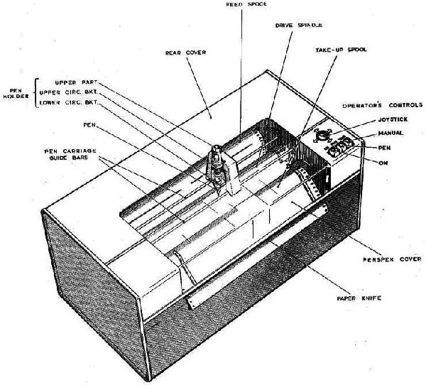
The paper passes over a long thin drive spindle (between long thin servo controlled feed & take up spools) which is completely different to the large drum used on some plotters. So there is no possibility of simply sticking a piece of A4 to the drum.
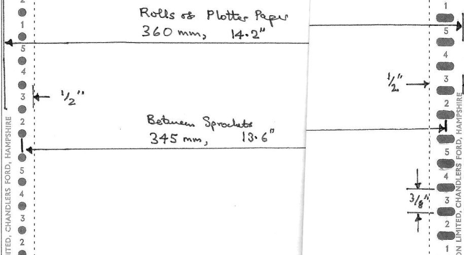
Here is sample of this paper (folded to fit into an A4 scanner). The plotter paper is 360mm wide and comes as a 150 foot roll.
 |
 |
The most important dimensions relate to the sprocket holes. These are 345mm apart from side to side, with a pitch of 3/8 inch, in contrast to the ½ inch pitch of lineprinter paper. The sprocket holes (not necessarily oval) are on ½ inch tear off edges but this is unimportant.
The part roll of paper that I have is probably slightly glossier than lineprinter paper. It not ruled, but graph paper was also available. Either would do. The plotter has a resolution of 200 increments per inch and draws at 300 increments per second.
My local GP’s ECG machine uses A4-sized fanfold so that won’t fit! If anyone knows where there is a secret horde of suitable paper, or of anyone who might still be making it, I’d love to know. My email address is ccs@tjf.org.uk.
In Resurrection 53 we reported the sale of an Apple 1 for £133,250. Now another, this time a working example, has come up for auction at Sotheby’s which fetched an astonishing £240,929. See www.bbc.co.uk/news/technology- 18456746.
-101010101-
The establishment to which I have referred elsewhere as BT’s Research Centre at Martlesham Heath is more properly known as Adastral Park. Located there is an organisation called Adastral Park Sports and Leisure: Atlas for short. So there is an Atlas Sports Hall, an Atlas Clubhouse and an Atlas Fitness Centre. Just for good measure, there is a Pegasus Tower, an Orion Building and a Sirius House. Where have we heard those names before I wonder?
-101010101-
The centenary of Turing’s birth on 23rd June was celebrated by a large number of events and lectures throughout the world. The sheer number of events is breathtaking. www.mathcomp.leeds.ac.uk/turing2012/give-page.php?13 has a list of no fewer than 171 of them — far too many to cover here so we will confine ourselves to a few arbitrary headlines —
Most of these essays pay extravagant tribute to Turing and his work but Simon Lavington’s Father of Computing? essay takes a rather more down to earth view. Though Pilot ACE was, when optimally programmed, very fast by the standards of the time, it was immensely difficult to achieve such speeds. Nor did the design allow for the possibility of future technological advance. Something of a blind alley then. Simon also quotes Max Newman’s view that Turing’s famous On Computable Numbers paper had but little influence on the development of computer design.
Jack Copeland chose the anniversary to put forward an equally controversial view that Turing’s supposed suicide might not have been all it seemed. At (dead hyperlink - http://global.oup.com/uk/pdf/general/popularscience/jackcopelandjune) he argues very plausibly that it is just as likely that his death was, as Turing’s mother protested at the time, a tragic accident.
By the end of May, 778 copies of the CCS publication Alan Turing and his Contemporaries had been sold bringing it to within a hair’s breath of a financial break-even point.
The London Science Museum’s special exhibition telling Turing’s story opened in June and will run for a year. It is a well thought out set of artefacts, each faultlessly described covering all the major events and achievements of Turing’s life. Your editor visited on a dull Monday morning and was encouraged to see so many people taking an interest.
Three further Turing blue plaques have been unveiled at Manchester University, Trinity College Cambridge and St Leonards to add to those at Wilmslow, Hampton, Guildford and Maida Vale. Nothing here in sunny Teddington yet. Perhaps when it stops raining.
-101010101-
Our friends at the LEO Society write to tell us about the sad death of Ernest Kaye who, as John Pinkerton’s assistant was responsible for much of the circuitry of LEO 1.
 |
This year marks the 50th anniversary of the Ferranti Atlas computer. In 1962 Atlas was reckoned to be the world’s most powerful supercomputer; a splendid excuse to hold a celebration from 4th to 6th December in Manchester. The main event will be a symposium, for which the speakers will be Dai Edwards, Brian Hardisty, David Hartley, David Howarth, Keith Jeffery, Simon Lavington and Dik Leatherdale. The topics covered include the historical timeframe; the hardware and software of the Atlas 1 & Atlas 2; marketing and installations; the users and applications.
There will be an accompanying exhibition of significant Atlas artefacts, photos and documents, and also demonstrations of an Atlas simulator. A social programme is being arranged. This will include special demonstrations of the 1948 Manchester Baby (the SSEM) and Hartree’s Differential Analyser at the Museum of Science & Industry (MOSI), an informal party, and some archival recording sessions with Atlas pioneers.
The Manchester event will bring together, probably for the last time, a unique group of industrialists, academics and end users who contributed to a world class project which made a beneficial impact upon the UK’s scientific computing resources in the 1960s. There will be no charge for attending the main symposium, though prior registration is required. Full details will be found at www.cs.manchester.ac.uk/Atlas50/.
As part of this year’s Cheltenham Science Festival in Cheltenham Town Hall, the GCHQ Historical Section challenged the Bombe Rebuild Team at Bletchley Park to intercept messages and from these intercepts to find the daily Enigma settings (the Key of the Day) in a manner as close as possible to that used during WWII. Once found, the Key of the Day was to be used to decipher messages from the general public visiting the Science Festival who had enciphered them on a genuine German Enigma. GCHQ staff wished to emphasise to the visitors their very important and historic successes back to and before WWII.
From the outset it was agreed that there would be no ‘cheating’ and this was upheld. However there had to be a couple of compromises: GCHQ had only one usable Enigma and it had a limited repertoire of usable wheels and we at Bletchley Park had only one Bombe not the nearly 200 available daily during the war. Furthermore, during the war Bletchley Park built up a great deal of knowledge about the way a particular Enigma network operated including, from previous decrypts, text that was regularly used in messages on that network. Such text was called a ‘crib’. Such a knowledge base was impracticable to emulate during the Festival. It was therefore agreed that GCHQ would send a message with known content each day and would keep to one wheel order for the week.
It should be noted that that during the war, with the German Enigma settings changing at midnight each day, intense effort was required at Bletchley Park and the outstations to find the new Key of the Day as quickly as possible. It is on record that the Keys of the Day of the most important networks were found regularly by 4 o’clock in the morning, so we set ourselves a target of four hours although in our case we did not start our processing until about 9am. We were successful in finding the keys every day and the times taken are listed at the end of this note.
Finding the Key of the Day is more complex than many people realise. It is not a case of feeding the enciphered message into the Bombe and having the plain text come out the other end. Far from it.
The stages we went through are as follows:
Once all the settings of the Key of the Day were found and a trial message deciphered, we were ready to decipher all the public’s messages that had built up in the meantime. When those were deciphered, new messages could also be deciphered in real time and sent back to Cheltenham Town Hall.
Just as Bletchley Park did in WWII, we used a British TypeX modified to emulate the German Enigma for our deciphering. We plugged up the stecker board and set the rings of the wheels in accordance with the Key of the Day. TypeX has both input and output print heads printing onto paper tape. Decrypts on the printed output tape were glued onto the message sheet thus avoiding any errors. There is a restriction in our modification of the TypeX as Enigma which rendered some messages undecipherable. In those few occasions we resorted to the Enigma-E (an electronic version of the Enigma) or to a software simulation of Enigma.
GCHQ had school children and interested adults enciphering their own messages on the Enigma machine and, by the afternoon, we were able to return the plain text messages in minutes. We used Twitter to send back the deciphered messages to Cheltenham.
Throughout the week we had a two way video link set up using Skype, good Webcams and a large screen display at each location.
During the weekdays, enciphered messages were sent to us using Twitter but on the Saturday and Sunday a radio Morse link was set up between the Cheltenham Radio Society (CARA) and the Milton Keynes Radio Society (MKARS). Many enciphered messages were sent by this method on Saturday but unfortunately on Sunday propagation issues beyond anybody’s control prevented us from receiving messages by this method. But that, as they say, is another story.
Considering the rebuilt Bombe itself, it had a great deal of work to do during the week but never let us down. We did have a stuck sense relay but this was soon identified and put right. It did not cause us to miss a stop but could have and this would have triggered a further investigation. Other minor problems were due to such things as a cable having its pins bent due to being damaged by accident. These sorts of problems are to be expected and we are told that such problems are very similar to those that happened during the war.
| Monday 11th | 3 hours 53 minutes | Rehearsal day |
| Tuesday 12th | 2 hours 42 minutes | |
| Wednesday 13th | 5 hours 42 minutes | |
| Thursday 14th | 3 hours 34 minutes | |
| Friday 15th | 2 hours 28 minutes | |
| Saturday 16th | 2 hours 25 minutes | Subsequent intercepts received over the air in Morse |
| Sunday 17th | 2 hours 45 minutes |
We continue Hamish Carmichael’s exposition of some of the dead-end and yet wondrous machines produced by the Powers Samas company.
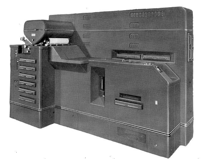 |
This mighty beast was supposed to be the tabulator to end all tabulators, but I believe the only end it really achieved was the end of Powers Samas. It was launched, perhaps prematurely, in 1956, and I’ve always understood that the excessive expenditure which its full development required was more than the company could afford, so that the merger with BTM in 1958/59 was more of a takeover.
I spent part of October 1958 running several Samastronics as an operator on the testing floor at the Aurelia Road factory in Croydon, in preparation for demonstrating one at the major Electronic Computer Exhibition at Olympia in November of that year.
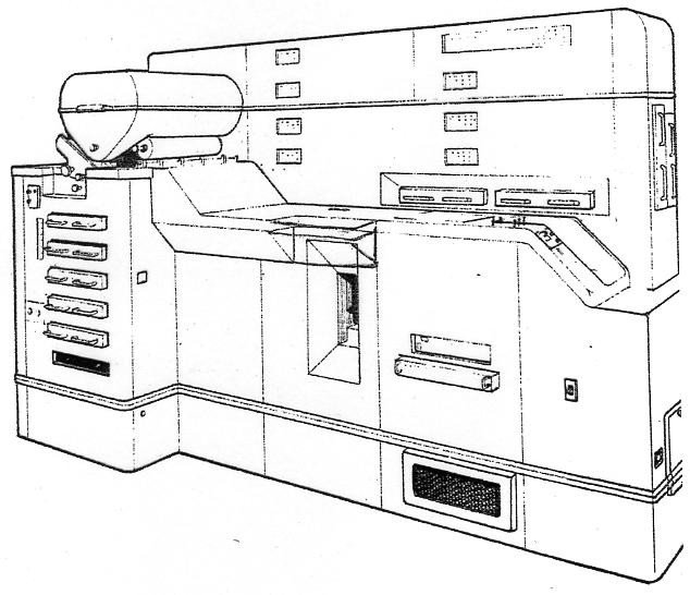
The taller section at the right of the machine contained the card track, the columnar decoders which interpreted the content of a card column into electronic form, the arithmetic units and the control logic which hung it all together.
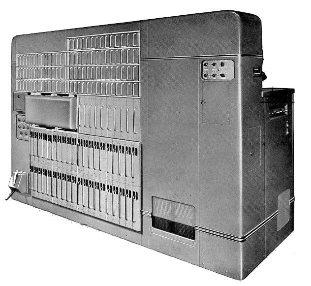 |
Rear View |
The card track was fairly conventional: there were two sensing stations, the first to control totalling and the second to read the data required for adding and printing. Three levels of totals could be taken. (I think it must have been about 1910, when Powers produced its second or third model of tabulator, that the total-controlling mechanism was added, and at that stage it was fairly called an Attachment; 50 years later, after generations of tabulators with this facility provided as standard, it was still called the ATA - the Automatic Totalling Attachment.) Cards were fed at 300 per minute. There were two receiving stackers, which operated alternately - when the first was full the flow switched to the second. This certainly made it easier for the operator to empty them without interrupting the flow of cards.
There were seven adding/subtracting units in the basic machine, and they could be specified as having either ten or thirteen digits If that wasn’t enough, additional arithmetic units could be specified, which would have been housed in a separate cabinet. I haven’t found out if anybody ever required them.
Most of the elements shown here were the columnar decoders, which turned the signals read from card columns into the form needed for internal working. They always seemed surprisingly large, and I think that must have been because the internal technology of the decoders was based on relays which must have been nearing the end of their life as a generally accepted technology. I’ve no evidence for this, but I think they would have been chosen because there was something more familiar and comfortable to the Powers Samas mind about a component which had a visible bit of physical movement to it.
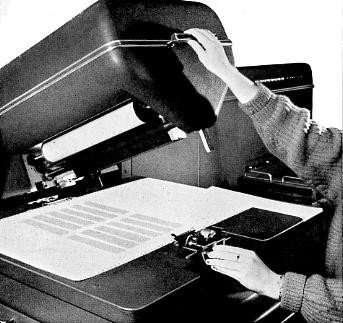 |
And so we come to the real glory bit - the printing mechanism. The printing head is shown here in the raised position. The essential heart of this was a bar which oscillated laterally across the print bed, at the same time as the paper was moving steadily forward. The bar carried 140 styli, one for each possible character position. The combined effect of the two movements was that each stylus executed a zigzag trace across one character width of the paper.
There could be a single carriage, as shown here, enabling printing to be generated at the full fourteen inch width. But there was also an option to have two independent print carriages side by side. These could be used, for example, to print full invoices on one carriage, while the other listed invoice summaries showing just account number and total.
It could print on multi part paper with interleaved carbons, with original and one or two carbon copies. Or instead of interleaving, there was an option of a carbon creep mechanism, which economised on the use of carbon at the expense of increased mechanical complexity.
Line spacing could be set at either six or eight lines to the inch. This was easily managed by varying the speed at which the paper was moved.
There was also a facility to speed up the paper movement for a particular line, producing elongated characters for emphasis.
Each stylus was actuated by its own solenoid, so a printed character was made up of a series of dots created at the appropriate points on the zigzag trace. The impulses to the solenoids were generated by character discs, non conducting material with metal inserts at appropriate points round the rim, energised from a common source. They were read by brushes. Brush sensing in a Powers machine! Whatever next?
Printing operated at 300 lines per minute. The oscillating bar executed 22 passes across the character space for each line; 15 passes were used to generate the character, the other seven for the interline space. I work out from that that the time available for a solenoid to generate a dot and recover ready for the next dot was about 1.8 milliseconds, which sounds pretty challenging.
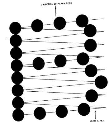 |
A little subtlety: the zigzag trace meant that any horizontal lines in a character - capital B for example - were not truly horizontal. It was found psychologically preferable for such lines to be generated on the pass which goes upward from left to right.
The repertoire allowed the generation of 50 different characters. The standard set comprised A to Z, 0 to 9, ¼, ½, ¾ (for dealing with farthings), 10, 11 (pence), %, +, -, £, (, ), & and *.
The use of character discs meant that it was easy to generate non standard characters, such as the accented ‘a’s and ‘o’s in the Swedish language.
 |
At many places around the machine there were slots to accept electronic connection units - ECUs, which linked the various functions of the machine together in an application specific way. This was explained as maximising the flexibility of the machine, but a cynic would say that the designers weren’t sure how to link the units together so left it for the user to decide. Each ECU could be plugged up by the user or bought pre-wired from the factory.
Another rather nifty feature was the phrase printing facility. A phrase of up to 32 characters could be set up in a special store, and its printing could be triggered by a control hole in an appropriate card.
There was supposed to be a dedicated summary card punch designed to work at the same speed as the tabulator. I never saw one, and I don’t know if it ever actually saw the light of day.
As I said earlier, we proudly demonstrated this marvellous device at Olympia in November 1958, expecting the rest of the world to be staggered by its speed of printing. So it was bad luck that at the same event Rank was able to demonstrate its mighty Xeronic printer, the first public appearance in the UK of the principle of xerographic printing. Although an experimental prototype it was much faster than our machine - 1,500 lines per minute, and they expected to crank it up to 3,000 lines per minute. But at least ours didn’t catch fire so often.
So the Samastronic was never the commercial success the company had hoped for. I believe it suffered from terrible reliability problems. There was a subsidiary sales line, making the printing mechanism on its own available as a peripheral for other people’s computers, but that didn’t do well either. I have heard of a normally phlegmatic Swedish customer getting apoplectic with rage over it, and most people who came into contact with it have their own horror stories. R.I.P.
This is probably the most interesting of the machines described here, because it was unlike anything else in the punched card world. It gets its name from a Mr E.T. McClure, about whom very little is known apart from his name. I believe he may have been Australian, but can’t be sure. And it’s not clear whether he worked for Powers Samas at the factory in Aurelia Road in Croydon, or whether he sold his invention to the company before lapsing into obscurity. What we do know is that he built a prototype of his multiplier in 1934, and that Powers Samas brought out a production version in 1938.
But to set it in context : Leibniz in the late 1600s is generally credited with inventing the method of multiplication involving successive addition and shifting of the multiplicand, which probably still goes on below the surface of most of the multiplications carried out to this day. It’s simple and effective, but the number of cycles it requires depends on the values of the digits of the multiplier, so it can be expensive in machine time. Therefore over the centuries many people have tried to devise a method of more direct multiplication.
Here are the names of just a few of them, all of whom devised machines that worked, though none of them made their inventors into millionaires.
Edmund Barbour of Boston, Massachusetts, filed patents in 1872 for a multiplier with a sliding carriage, multiple pinions and mutilated gear racks, the arrangement of the teeth serving as multiples of the digit they represent. He subsequently patented an associated printing mechanism.
Ramon Verea was a Spaniard who moved via Cuba to New York just after the American Civil War. His motivation seems to have been national pride: Spanish brains ought to be able to invent things that would restore Spain’s former national superiority. In 1878 he produced a direct multiplier based on a ten sided cylinder, each side having a column of holes with ten different diameters. The notes say that it worked rather like a Jacquard loom.
Léon Bollée, a very versatile Frenchman, devised several interesting machines. The Direct Multiplier used a number of bars with attached pins with different lengths - somewhat like a mechanical representation of Napier’s bones. In operation the pins came into contact with gear strips which moved by different amounts depending on the heights of the pins. In 1892 he demonstrated his machine calculating automatically the square root of an 18 digit number in about 30 seconds.
Otto Steiger patented his Millionaire in 1892. It used a mechanical representation of the multiplication table to form partial products. These were passed through a transmitting mechanism to a combining and registering mechanism to display the result to the operator. A trained operator was able to multiply two eight digit numbers in about seven seconds. Unlike the preceding machines this one went on to become commercial and, although very expensive, remained in production until 1935.
 |
So from what we have seen, the McClure Multiplying Punch was not unique, except in one aspect - it worked in sterling. Ah, how complicated we used to make things for ourselves!
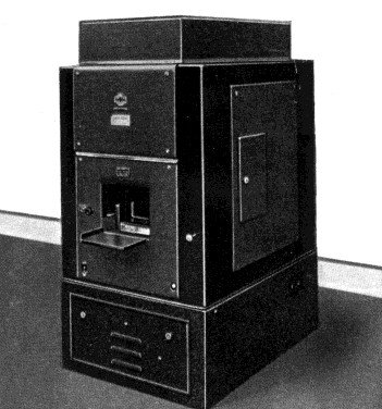
This is not perhaps the most informative picture, but it does at least prove that the thing did exist. And it actually looks not unlike the later EMP - the Electronic Multiplying Punch - which emerged to perform the same functions in the mid 1950s.
Product Tables
What the machine was trying to achieve was a form of mechanical lookup from a table showing the results of every possible combination of digits from the multiplier and multiplicand
Some say this way of tabulating the results of all possible multiplications goes back to Pythagoras.
Maybe so, but at least Pythagoras didn’t do the same job for sterling multiplications.
The crucial step was to convert each line of the product tables into a stepped profile, with the height of each step corresponding to the numerical value.
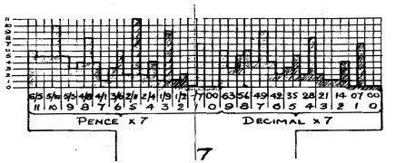 |
The picture shows the product profile for the ‘times seven’ line, with pence on the left and ordinary decimals on the right.
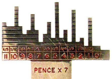 |
But here’s a picture of an actual pence profile plate, again from the ‘times seven’ line. You can hopefully just see that each product has a two digit form, the left hand digit representing shillings and the right hand one pennies. Twice seven pence = 14 pence = one shilling and tuppence; it takes you back a bit, doesn’t it?
Configuration
We’re looking at the multiplier end of the calculating head. The multiplicand would be behind this.
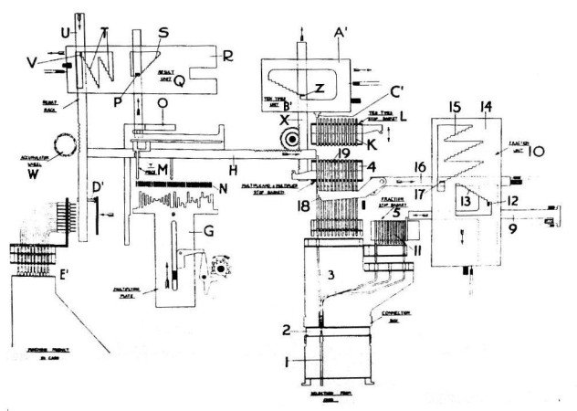 |
The information comes up from the card through a connection box into stop baskets in Powers conventional manner. On the reading cycle the multiplier is read into the multiplier stop basket, which we can see, while the multiplicand is set up in the multiplicand stop basket behind it. A control is also set up to say how many digits there are in the multiplier, and therefore how many multiplying cycles will be required.
On a multiplying cycle the appropriate multiplier feeler bar moves forward until it meets the stop in the stop basket. In this case it meets the 9 stop. This causes the 9 profile plate to be raised into the active position. We can see (just) that this is a compound plate, with decimal values to the left and the sterling profile to the right.
The multiplicand feeler bars similarly move forward until they are arrested by the raised stops in the multiplicand stop basket. They then send fingers down to sense the relevant parts of the profile plate. That vertical movement is transferred via the result plates to the vertical result bars, and the extent to which they move is picked up by the accumulator wheels.
The multiplicand is also moved, via Bowden cables which are not shown here, to the 10 times unit. The stops in the multiplicand stop basket are cleared, and on the next cycle the multiplicand feeler bars sense the value of the shifted multiplicand from the stops in the ten times unit.
When all multiplying cycles have been completed, the finished product is read off the accumulator wheels and passed to the punch unit, where the card has been waiting to receive the answer. At the same time the next card is being read.
Multiplying in 3D
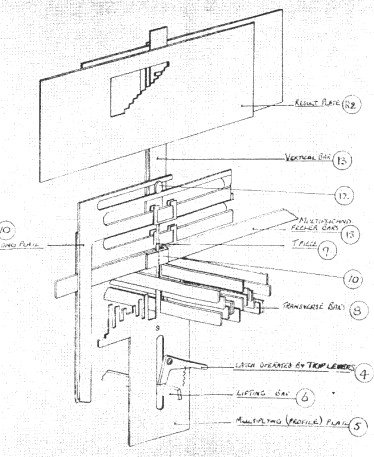 |
This shows how the multiplicand feeler bars sense the profile plate by means of transverse bars which run across the whole width of the multiplicand. And that movement is registered by where the stud on the vertical bar meets the stepped profile in the result plate.
This is the key to the business of carrying. Each product, read off the profile plate, has two digits, one to be registered in the relevant digit, and one to be added on to the digit on its left. There is a subtlety by which each unit is able to nudge the result plate of its neighbour on the left, so that what gets added to the accumulator wheels is the arithmetically correct combination of figures.
For example, multiplying 25 by 5 - the units product is 25, the tens product is 10. And by the nudge the 2 is added into the tens position, giving the correct product of 125.
Throughput depended on the size of the multiplier. Rates of 1,560, 1,040, 780, 624 and 520 cards per hour could be achieved as the number of digits in the multiplier varied for one to five. This was the justification of the whole machine. The performance depends only on the number of digits in the multiplier. The value of those digits does not matter.
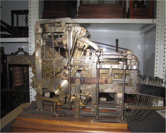 |
This splendid piece of kit, which McClure used to demonstrate the principles of his invention, was presented to the Museum in 1938, and currently lives in Blythe House. As far as I can make out, it differs a great deal from the production version of the machine. There’s a keyboard with which to enter the multiplicand. When that has been registered the same keyboard can be used to enter a digit of the multiplier. And there’s a handwheel to make it move through the process of multiplication. But, of course, in the Museum’s eyes it’s not a machine; it’s an object. So even with white gloves you’re not allowed to touch the keyboard, let alone turn the handwheel. Shame!
One final point: There’s a letter, dated 16th October 1957, from A.R.W. Hill, Manager Local Government and Public Utilities Dept of Powers Samas Accounting Machines, to the Science Museum:
“I remember that you have some of the original McClure multiplying mechanism in the gallery. In this connection you may be interested to know that the South Eastern Electricity Board has for disposal now one of the early Powers Samas machines constructed on this principle. As an accounting machine it now has no value, and I fondly imagine the Electricity Board would be happy to donate it to the Museum if you were interested. The machine of course has special interest since it is a specimen of a very small range of machines built to operate on a table lookup principle and which of course has now been superseded by electronic calculators and will never again be built.”
But I don’t believe the Museum took up the offer, and so the McClure Multiplying Punch is probably now as dead as the dodo.
This is the second part of an edited transcript of the presentation given at the Science Museum on 19th January 2012. Hamish Carmichael can be contacted at hamishc@globalnet.co.uk.
Before George 3 was (eventually) released ICL 1900 users had the benefit of a rather lightweight interactive development environment “Minimop” which typically ran alongside George 2. This is the unlikely story of how something more “up to the job” was developed.
The Queen Mary College (University of London) Computer Centre had started ICL operations in mid-1968 with a shiny new 1905E running a (mostly Fortran) batch service under Operator’s Executive [Exec], with JEAN offering a lightweight interactive programming system to teletype users for teaching. The initial configuration was: 64K words of memory, three EDS4 exchangeable disc drives, a complete set of paper handling peripherals (TR, TP, CR. CP and LP), four 7-track tape decks and most importantly a 9-channel Multiplexor [MUX] with a set of 10 cps (110 baud 80-0-80v) teletypes. The strategy was to switch to George 3 and its built-in Multiple Online Programming facility [G3-MOP] as soon as generally released. However, G3 development was clearly getting later and later, so the College would have to make do with George 2 [G2] for simple batch automation and Minimop as the interactive service; both of which were introduced during the 1968/9 academic year. G2 was quite effective once a good set of macros had been written. But Minimop, which offered simple input, edit, compile and run facilities (roughly comparable to what G2 did in batch mode) for interactive users by time slicing and swapping program images to/from disc - simply clunked. For example, JEAN was still available under Minimop as a single user application, but swapping nine copies of that in and out from the EDS4s roughly added a zero to its average response time.
We managed to get copies of the PLAN source code of Minimop in the hope that we could ‘help ICL to improve it’. While the coding looked adequate, if a little quirky, the fundamental problem was the architecture. Although written for multithreading (by having a dedicated set of work locations dedicated to each user process - called ‘V-store’), it was in practice little more multitasking than a traditional double-buffered batch processing program, and as a result allowed itself to be suspended by Exec whenever a required I/O operation had not yet completed. So the decision was taken to see if we could write a (Minimop) user interface and filestore compatible clone that would run (a lot) faster - i.e. to maximise the potential of Minimop. Thus the Maximop idea was born.
Jeremy Brandon had done a lot of investigations and tests in early 1970, and came up with a brilliant outline system design that would exploit all the (then) available Exec facilities for real time systems.
The program would run as three subprograms or ‘program members’:
member zero (0#) at the lowest priority (96) would run the (user) programs-under-control (PUCs) and handle all ‘slow’ interactions with Exec on behalf of the other members (e.g. file open, close, renames, console displays, etc);
member one (1#) - priority 97 - would do all command processing and system co-ordination;
while member two (2#) - priority 98 - would do all communications handling - all in memory (no overlays) and would never perform any disc I/O or do anything else likely to get itself suspended.
In order to bypass Exec’s 16/32 simultaneously open files limit (even for a trusted program) we would exploit a trick (permitted in a 1900 format disc’s system control area) of doubly defining the whole of the user files area with an ‘umbrella file’; and would then preserve user file access locking and integrity by a development of the secure file hiding by renaming technique that we already perfected for the offline user files swapping mechanism to support Minimop.
0# and 1# would (have to be) overlaid (and the overlays would be 256 words each), and all in lower memory (i.e. below 4K) for direct access to local storage;
1# and 2# would be written to run (only) in compact (15-bit) mode for speed and size;
only 0# would be mode compatible in order to support PUCs above the 32K limit (i.e. coded to be able to execute in either 15 or 22-bit mode according to configuration);
no extended mode instructions (like MVCH or BCT) would be used; partly because on the 1905E we knew their ‘add-on’ implementation was very slow, but perhaps more importantly because they were not range compatible and we had already received an expression of interest from at least one other University (East Anglia) to take our system as a potential way of properly supporting their Micro 16V front end processor implementation - and they like many of the other 1900 Universities User Group members only had either a 1905 or 1909 compact mode processor;
everything possible would be put into lower memory for fast direct access;
the members would communicate with each other exclusively through a set of Knuth semaphores;
only 0# was allowed to do anything that might (under normal operation) cause it to become suspended;
the system was to support a theoretical maximum number of 63 terminals (a vast capability upgrade when we only had a 9-channel MUX, and Minimop clearly could not even support them properly on the 1905E); and of these only a much smaller (configurable) number of users could actually be logged in simultaneously (perhaps 30% to 50%); and an even smaller (again configurable) number of those would simultaneously be able run an application or user program;
at least initially, the system must be 100% Minimop filestore, user interface and application program/utility compatible;
coding would be done in GIN (the sophisticated G3 macro assembler) because we needed better (fine) control of object code and overlays than PLAN provided - and proper macros;
as much work as possible would be done by the compiler in order to give us both the tightest possible code and the greatest possible configurability (e.g. absolutely no hard coded constants allowed except as #DEFINEs. Wherever practicable conditional compilation would be used to tailor the code to the configuration rather by coding runtime conditionals);
all code must be fully re-entrant; however, it was subsequently realised that by the nature of their tasks and that of the Exec interface for PUCs, this rule was an unnecessary complication/restriction for the 0# overlays and was therefore relaxed to allow things like preset PERI Control Area templates inside the overlays;
memory for I/O buffers was very precious and their use needed to be very carefully managed so a strict (deadly embraceproof) ‘banker’s algorithm’ approach was adopted for their short term rental by the command processes in which the absolute maximum any process could ever have simultaneously was two 128 character information buffers (I-BUFs, e.g. for input and output text lines), plus two 128 word (one block) disc buffers (E-BUFs) - just enough resources to implement, say, a copy-and-amend style text edit (most processes only using half that amount);
finally, the team’s mantra: “Modularise - Orthogonalise - Parameterise” was emblazoned across the top of the systems office blackboard.
The original Maximop Development Team consisted of just four of us: Jeremy Brandon (Chief Programmer and Design Authority), Arthur Dransfield (Systems Programmer and Technical Authority), Bob Jones and Dave Pick (both at that time students). Bob and Dave became full time staff on graduation, and this became the Maximop team until further notice. None of us was actually full time on Maximop after the first few months.
In subsequent years, several members of the user support/applications teams also did a lot of good work on replacing the old ICL Minimop utilities and applications with better versions. Two significant additions to the systems team in those follow-on years were Paul Godfrey (built in Editor and Maxi-Batch guru) and John Cobb (especially on support and maintenance). [But that is not to denigrate the huge user applications support and development efforts put in by people like Geoff Cooper, Tony Law, et al.]
The four of us started Maximop work in earnest on the first day of the summer vacation 1970. We spent a few days brainstorming, and roughly documented some outline implementation details like the use of global identifiers, naming conventions, coding style and preferred register usage. Then Jeremy and Bob tackled the 0# basic control and PUC handing modules; Dave started on 1# control structures; and I tackled the 2# control routines and implemented Jeremy’s pre-designed MUX channel handling algorithm. To begin with we relied on some rather crude compiler generated static data tables to test against. One of my next jobs was to write the extensive start-up overlays to configure and initialise all the dynamic data structures, etc, before going to develop many of the 1# command handling overlays (e.g. login/file open) alongside Dave, who was already well into some of the key command overlays (those. with most stringent performance needs) like Input, List and Print. Dave was an absolute wizard with the GIN macro language and exploiting the GIN ‘compiler variables’, and quickly produced us a very rich and programmer-friendly set of macros that greatly simplified everyday coding tasks, while idiot proofing repetitive things like overlay segment addressing and numbering, and overlay file block management.
Perhaps a little our own surprise, after only a very few weeks coding and compiler wrestling we had a skeleton operating system that seemed to work - and worked well! By the end of that summer vacation when Dave and Bob had to go back to the real (student) world for a while, we had a basic system that had already more than satisfied the proof of concept requirements - Mark 0 was alive and kicking. During that autumn of 1970, Jeremy and I, with quite a lot of unofficial work from Dave and Bob (official during Christmas vacation), worked steadily to fill in all the gaps that Maximop needed in order to be regarded as a plug-in replacement for Minimop.
Our principal live systems testing slots were typically just the one hour starting at either 17:00 or 17:30 on as many evenings a week as we wanted. Confidence grew as all the pieces fell into place one by one so that by early 1971 we were inviting other staff and trusted users to try out the system for themselves during many of the ‘systems sessions’. Eventually, the Manager (Vic Green) and Director (Prof. Isaac Khabaza) were convinced enough to allow us to instruct the operators to bring up Maximop Mark 0J, instead of Minimop, as the production service at 09:00 on Monday 15th February 1971 (yes, coincidentally that was also ‘Decimal Day’ when other things changed forever). We watched the system nervously all morning with the rollback instructions sitting ready by the operator’s console. They were never used. Minimop never ran again in production at QMC.
After a few months running and further refinement we offered to give the system ‘as is’ to all the other members of the ICL 1900 Universities User Group. I had naively assumed we would get just a handful of tentative takers (e.g. like East Anglia who wanted to add their Micro 16V interface code in to 2#). In fact, almost everyone there put their hand up to receive a tape and instructions in order to try it out - which, of course, caused us a little administrative problem. The future of Minimop in universities almost certainly ended that day. Luckily for us, ICL Universities Sales Region got the message very quickly and took over all front line support and distribution from us. Within only a couple of years there were over 100 Maximop systems running all around the (ICL) world - including, for example, three in Australia and one in Papua New Guinea. Very soon there was pressure to licence it to various government and commercial customers, and so after some heart searching about the commercial dimension, we agreed in exchange for heavily discounted extra hardware (money would have been much too politically difficult to handle). Thus all those pedantic ‘range compatible’ implementation criteria were actually worthwhile - at least for the first few years.
Meanwhile user demand at home rapidly exceeded capacity. The MUX became a 32 channel scanner, the EDS4s became EDS30s, the 1905E became a 1904S, a 7903 front end processor was added and more scanners; then a second 1904S twin processor was added with EDS60s an IPB and dynamic device switches - but all how that worked is quite another story.
However, as a result of all this growth, major upgrades were necessary (mostly to 2#), first to support ICL VDUs, then the 7903 and later ICL’s Comms Manager interface.
Quite soon the 63 terminals/users limit was reached and had to be upgraded to 512 (the next convenient 1900 hardware field size). Then we started to run out of lower memory in the larger compiled configurations - so all of 2#’s neat little fixed lower data tables had to be moved into dynamic upper storage. Mercifully, each of these apparently significant changes was surprisingly easy to implement, very largely because of the parametric, orthogonal modularity we had built in to both the architecture and the coding from day one.
The expected source size of Maximop meant that we had no practical choice but to create it all as a structured (sub-file format) magnetic tape. In practice this was the only way that GIN could compile anything bigger than a punched card deck. But that, of course, meant tape-to-tape line mode sub-files input and editing from punched cards - which inevitably meant overnight G2 batch jobs.
As a result a typical cycle to build and test a new Maximop version in the beginning would something like:
day 1: design and outline new code segment - perhaps have time to start detailed coding
day 2, 3, ..: finish detailed coding and then punch the cards; [Now in those days there was a data punching service available - but that meant neat hand writing on coding sheets (without any programmers shorthand), which took much longer than simply bashing one of the IBM 029 key punches for a few hours, often filling out the comments as we went];
day n: write (and punch) the tape editing instructions around the new code, then put together compile pack and job description, submit batch job and go home (sometimes via College Bar);
day n+1: read compiler printout and error reports; either clean up the same edit/compile job deck and resubmit or create an incremental job according to the nature/extent of the damage; submit next batch job and go home;
day n+2: check now perfect compiler listing(!); book testing slot for that evening; prepare test notes/scripts and data; then at 17:00 bring up new system in test mode - try it all out; if going well do a bit of regression testing; log any issues and failures; take post mortem prints as necessary (sometime take a post mortem even if all seemed well in order to check that things had worked for the right reason/in the expected way);
day n+2: review test results, post mortems; find bugs; solve problems; write/punch edits to fix/improve code; prepare for next batch edit/compile run;
... and so on.
Usually we managed to get quite large chunks of code through the cycle in about a working week; and of course, with up to four of us working more or less in parallel each overnight edit/compile run typically had components for several independent features all at different stages of the cycle. Most of the time we managed not to stop each other from being able to test our respective updates, even if some of them had still system crashing bugs just waiting to be found.
With this length of build cycle it should come as no surprise that we very quickly developed great skill and some very useful tools to mend and patch the builds in order to save yet another overnight run just to fix something small and/or silly.
Later on life got quite a bit easier - once we had Maximop up, running and stable; a fair amount of online user file space each; a (glass) terminal on each desk; a good online text editor; and an application that could submit ‘card less’ G2 batch jobs directly from Maximop. But, of course, we always still had to run an overnight batch job to handle the tapes and recompile the whole system at several points in every cycle.
Another great boost to development/maintenance productivity was the addition of the ‘master terminal’ mechanism, whereby one of the office terminals could be designated as having all the same privileges (at least within Maximop) as were available from the operators’ console in the machine room - without getting in their way while handling all the batch jobs.
Another great time saver was the early development of a very comprehensive post mortem printout facility that presented all the working storage in a logically structured and well annotated format. The post mortem overlay loaded and invoked by the inevitable operator command GO#MAXI 23 was almost as large as the extensive Setup code that had built and which populated all the runtime data structures. At the end of any post mortem print the operators could immediately restart the system simple by another GO#... command to load a clean copy of the setup routines. The first thing that Setup always did was tidy up anything and everything that might have been left from any previous broken session (e.g. unlocking the dynamically hidden files) whether that had been hardware or software induced - with or without a successful post mortem.
As well as being able to fine tune a lot of the installation parameters in flight (often from the master terminal), we also added a runtime #MEND command that could examine or change to any word in any part of the system (including overlays, setup and post mortem) either just in memory or permanently written back to the overlay file. Very dangerous - but oh how very useful! On many occasions once we had identified the cause of some unexpected behaviour, event or system crash, it would turn out to be just one or two wrong or missing instructions. Should we wait until scheduled end of service to apply the necessary patch(es) - and risk it happening again in the meanwhile? or should we try and patch it in flight? So confident were we of the system’s resilience; of our in depth understanding of its behaviour; and of our ability to write perfect octal patches(!), that we usually chose the latter option. First one of us would write the required GIN source code #MEND command patch for the current restore pack - and then hand compile it into octal. Both would be carefully checked by someone else - sometimes with a third opinion. Then we would type all the required runtime #MEND commands into a macro: (a) so that the typing could be properly proof read, and (b) so that the macro could first be executed with patch-in-memory-only mode - possibly test the feature concerned (although not always a practicality) - and then finally (if we were still on the air) executed again with the write-back-to-disc option set. I cannot remember ever crashing the system when we did this. We knew we were good at it - but perhaps we were also a little bit lucky?
Debugging non trivial problems was often a communal brainstorming activity carried out in the Common Room over coffee rather than by poring over more post mortem dumps. For a long time we had been haunted by a very obscure lost buffer problem in 1#. One day talking through the complete illogicality of what we kept finding in the post mortems - for the umpteenth time that week, a passing comment was made to the effect that it was just as if register zero (X0) was being randomly cleared (when it should have contained the address of the current process’s newly allocated buffer). We realised that we had never seen nor had reason to suspect any other similar or random corruption of this type associated with this problem. Also as 1# could not realistically be doing this to itself (as this was part of a very long trusted common routine) that might mean systematic interference from another program member, and the most likely cause of that could be an instruction using a wrong (or unset) modifier index to access a dynamic data structure. Now whenever Exec changed the current program member, its registers and control words were saved into addresses (32 + 16 x member number) - i.e. 1#’s X0 would be dumped into word 48. So could anything be corrupting word 48? What an interesting number. Everyone sat up and we looked at each other in silence. The obvious candidate was something in 2# (as that most frequently interrupted 1#), but we knew there was simply no offset as big as 48 in any of 2#’s code of data structures, so that was rather improbable. But 0# on the other hand had just one data structure with offsets that big - in the PUC control block - and +48 was indeed one of its defined offsets (one of the J0PB... values). But, oh dear, how to find it in tens of thousands of lines of code that were not in themselves exhibiting any obvious problems to provide clues? The solution was put in a dummy overnight compile run with a #WRONG directive on the suspect identifier, and with the listing level turned down to errors only (which would show every instance of the named identifier as a ‘W’ pseudo-error). Next morning it only took five minutes to spot the one and only use of that offset without any obligatory modifier register ... and, of course, the necessary one word patch was then Mended into the system before that morning’s coffee time.
Arthur Dransfield started as a Systems Programmer on the ICL 1900 machine at QMC upon graduation in 1969 and rose to be Chief Programmer before pursuing a more varied career around the industry that included: five years as Head of the London Network Team (the University of London liaison to JANET’s Joint Network Team); and over 20 years with Logica plc, mostly in standards, software quality assurance and the TickIT Scheme, before retiring in 2010. He can be contacted at arthur.dransfield@bcs.org.
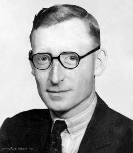
The name of Tommy Flowers will be known to Resurrection’s readers in connection with Colossus and for that work he is justly famous. His work with the Post Office following the war is perhaps, less well known to us and the circumstances of his departure from it less still. This article was first published as a letter to the editor in the Newsletter of the Retired Staff Section (RSS) of British Telecom’s research centre at Martlesham Heath in Suffolk, the successor to Dollis Hill. It appears by kind permission of the editor, David Cheeseman, as originally published.
 |
The very sad treatment, which Dr T. H. Flowers received from his employer in 1960 has not, to my knowledge, been told before. As it is entwined with the story of Empress [a telephone exchange in West London - Ed.], I thought that the recent publication about Empress was a good time to relate it. I was very close to the ‘scene of the crime’ and wish to record the story as I saw it, before the inevitable passage of time erases it completely. This is especially important when we now recall the splendid contribution he made to our war effort some 20 years earlier. Bear in mind, too, that his secret war work was, for national security reasons, probably unknown to the axemen making the chop on his career.
Peace arrived in 1945 finding many countries very poor and barely able to spend to improve their tired and stretched telephone systems. However, in a number of countries, research work was started on future designs of switching equipment. This was inspired by the immense strides made in electronics in the five years of war. It should be noted that not all of this experience was available to incorporate in new designs because some of it was still subject to wartime secrecy. Notable in this was the requirement to conceal all work done by Tommy Flowers at the Post Office Research Station at Dollis Hill. Incredibly the embargo on his speaking about the development of Colossus to ANYONE was not lifted until 1981 when Tommy was allowed to lecture at Martlesham Heath about Colossus for the first time. Nor do we know anything of his work on Radar for which he was security cleared in 1938. We note also that he travelled to Berlin in August 1939 for a pre-CCIF meeting that he described in Newsletter Vol 49 of January 1993. What was he doing there? He just scraped back home on the last boat train before the start of WWII.
After the war many proposals for new telephone systems were discussed and much optimism and ingenuity was visible in attempts to produce systems that were to be superior in facilities to the existing mechanical systems - and, always an important factor, at no greater cost. Although most proposed the use of a time division system to allow a switch to carry many channels (typically 30 or 100) it is now clear that valve technology was too cumbersome. None could possibly succeed until the invention of ‘transistor action’ in 1948 and the development of useable transistors half a dozen years later. Nevertheless, different countries and companies did favour their own particular but imperfect new systems. Their favoured ideas were presented at international forums and much animosity developed as fallacies were exposed in every claim for a suitable design.
The biggest problem for electronic systems was in dealing with the analogue voice signals. In earlier mechanical systems these were always carried on a pair of wires with a pair of switches at each switching crosspoint. These balanced pairs are naturally partly immune to any interference that affects each conductor in the same way, so that the interference cancels out. The new, electronic systems all tried, for cheapness to carry the pulses of analogue signals through the exchange on unbalanced pairs of a single wire, a switch and a common earth plane. This was such a mundane part of the design that few recognised that it was not possible to do this in a big exchange and achieve an adequate signal to noise ratio. A balanced pair would have meant twice as many switches and this increased costs that were already too high.
Most of the intellectual effort in developing new switching systems was directed to the more exotic aspects such as the control systems (e.g. fixed or programmable logic), or the hierarchy of the time division of the transmission path.
I remember spending some time with colleague and circuit wizard Jimmy French seeking a design for a noise immune electronic crosspoint. But we failed to find a solution to this self appointed task and reverted to the other work that Tommy had assigned to us. He was one of those few ‘Natural Leaders’ whom one would follow anywhere - even over the edge of a cliff as in this case. Thus, like everyone else, we shut our eyes to the impossible problem and kept on doing the pieces that were possible. After all, the rest of the world seemed to be content, why shouldn’t we be as well? After two decades of striving, the whole world was not much closer to a system for a fully electronic system for production. Management was getting impatient with engineers who always promised results for tomorrow. From where I sat in the middle of Tommy’s team we saw that the PO was about to decide to adopt halfway solutions with balanced pair crosspoints using reed relays or crossbar mechanical switches. All other developments that had promised so much and delivered so little were to be stopped.
So within Research Department at Dollis Hill someone had to tell Tommy. The task fell to the Director, R. J. Halsey. My guess is that, because he was a transmission man, he could see that it was not possible to get an adequate signal to noise ratio with an unbalanced switch if the return earth-plane was as large as a telephone exchange. Tommy was a determined man and I guess that he would not accept this decision. Having failed to persuade Tommy - I guess that Halsey felt that he had only one alternative - to move Tommy from his switching post and replace him with H. B. Law who was then running Radio Telegraphy.
At that time - 1964 - I was well positioned to hear all of the ‘underground’ messages. I had been working for Tommy for some time and shared an office with Doug Harding and long-serving Jack Hesketh. Their antennae were very sensitive to such matters. We heard that, even in his new radio post, Tommy was still attentive to his switching work that had occupied him for much of the earlier 25 years. We also knew that Winston Duerdoth who, although working for Tommy, had been allowed to work freely for some years on innovative PCM developments. His work had been noted in the city branches where it had been instrumental in guiding them to make radical changes to the transmission plan for the whole country. For that work Winston had been awarded a ‘merit promotion’ to Staff Engineer without the actual staff responsibility.
So when Harry Law took over the Switching Division he was presented with a way ahead. This was to use PCM (pulse code modulation), a system invented by Alec Reeves in 1937, in a radically new switching system already outlined by Winston. In this system signals could be switched using only one, unbalanced, switch per stage. This is because the analogue signal was sampled regularly and represented by a set of binary digits that could be made largely immune to interfering noise.
These PCM techniques had first been adopted for use in transmission systems because they allowed for the upgrading of analogue circuits to carry, say, 24 or 30 multi-channel circuits merely by the addition of repeaters and terminal equipments. It quickly became the transmission system of choice to supersede all other multi-channel systems.
The earlier work at Dollis Hill by Winston Duerdoth had begun to show some exciting possibilities for the switching of these PCM signals. Moreover, because the switching was applied to circuits already carrying PCM signals there was no extra cost in the codec (COder - DECoder) because this already existed for the transmission path. This meant that such an exchange might actually be cheaper than a mechanical one as well as having all the other advantages of electronics.
At Dollis Hill there was a small team of designers, previously working for Tommy, who were thrown free from his halted design of the ‘Low Speed’ 30 channel analogue system and they were, fortuitously, co-located with Duerdoth’s team. This was a dream starting point. A project for a PCM exchange switch was quickly agreed and tasks fell naturally to those with the appropriate skills. The experience already with the team ensured that the targets chosen were modest and quickly achievable. It was to be designed and built by the small team on the Dollis Hill site so communication and management control problems became insignificant. Names to note are Doug Harding and Winston Duerdoth who first became the pair leading the project under Harry Law. In the next layer were Jack Hesketh concerned with trunking and timing. Doug Thomson, Jimmy French. John Jarvis and Jack Kirkland worked to Winston Duerdoth and dealt with the digital space and time switches. Then there was Charles Hughes who had just joined us after a tour in Africa. He was showing an interest in the new subject of software. His responsibilities in Empress showed him the ‘fissures’ into which ‘microprocessors’ (which he was just about to invent) could be introduced into telephone systems. This deserves a paper of its own. Others in the team were Jork Andrews with storage and power supply and Bill Morton with technology and equipment design and production. Alan Ithell came in to the project soon after the start, He was charged with overall assembly and control of the field trial. This small team under Harry Law had no geographical separation and were able to take work into the field quickly and with a minimum of bureaucracy.
The choice of a PCM switch happened very quickly because it was such a natural development But Tommy was quick as well. He accepted an offer of employment by STC (the other partner of the PO in the halted analogue system). So, soon after his forced move to radiotelegraph work, he resigned from the PO and joined STC to continue to work on his favoured analogue system. We were stunned to hear of this decision on a Monday and that he was to leave the Post Office on Friday of that week. His old staff were very upset because it did not appear possible for him to be given a proper farewell ceremony that he so richly deserved. ‘Richly’ we thought, even though we knew nothing of his great wartime work at that time. John Jarvis and I decided to push hard to get enough contributions from his friends at Dollis Hill and down in the City to buy him a gold watch and force a formal ceremony where the Director would be obliged to make the presentation. Even the typing pool turned up trumps to get the notices in people’s in trays quickly. We collected over £40 and I went into town to buy his gold Omega watch.
The ceremony on Friday went well. I seem to remember that, in making the presentation, the Director avoided using the word gold for the watch. There seemed to be little affection between the two of them. However Frank Hewlett more than made up for it by standing up to make a very formal farewell speech dressed in his sailing club commodore’s jacket with his cap tucked under his arm. Tommy was, of course a member of the sailing club - but Frank spoke for everyone at that time. So we just managed to give Tommy a worthy farewell but we have no idea of the financial losses he suffered as a result of this hurried move, especially as STC soon saw the need to drop the development as unworkable. This seemed to leave Tommy with no connection with work at all worthy of him - he stopped work at STC in 1970. His career was thus brought to a sad end. If this was not a ‘sacking’ what else could you call it? Worse still when you remember that very few knew anything of his war work. Only a few of his staff such as Harry Fensom and Norman Thurlow had worked with him during the war and even they knew only as much as they needed to know to do their wartime jobs. They had no knowledge of the overall project that was Colossus.
In Bill Jones’ article in NL Vol. 97 he said that the design work for Empress was ‘tough going’ and that the time scales began to slip. I do not remember that. I think that we had all concentrated on our own pieces and the overall design might have been given less attention. It was Jack Hesketh who spoiled this and settled down with newly arrived Graham Oliver and some very large sheets of paper to produce a timing diagram for the whole exchange. To this we would all have to conform.
At about that time another new arrival was Michael Miller. Graham and Michael were products of the excellent Graduate Apprentice Scheme. Michael was directed to study, not just the problem of keeping four exchanges in synchronism for a field trial, but the synchronisation of the whole telecommunications network forever. For his work on digital exchange network synchronisation the University of Warwick awarded Michael a PhD.
A site nearby in West London at the Empress telephone exchange was chosen for the trial of the new exchange. This was a ‘tandem’ exchange so the new equipment was required only to switch traffic arriving in a 24 channel circuit from one exchange to the circuit going out to another. No customer equipment would be involved. The new exchange we were to build can now be seen to consist of interface equipments to the lines from each of four routes with a control system receiving information from the interfaces, instructing the switches and providing management and maintenance information.
There were stores to control the operation of the switches with the ever changing switching patterns required for each of the 24 channels, a power supply system and, of course, the switches themselves. Elements performing these functions had appeared in earlier exchange designs and it had been noted that some items, although thought to be trivial, had disappointed in their performance. Special attention was given to some items and over engineering rather than cost minimisation was employed.
Empress exchange was small and had a brief life of only about four years, but four years carrying live telephone traffic generated by real customers. In that time it proved to the world that this technique could be made to work reliably. It has been the model for all other telephone and Internet switching systems in the ensuing 40 years. However, the small size of the exchange and its short life has left few memories. Some parts of the exchange were salvaged by John Kendall and later thrust on such as me. I hope to pass mine on to Connected Earth museums in the hope that its place in history will not be forgotten. I like to think that it was Dr Flowers who produced the team that was capable of producing such a groundbreaking design, even if the switch was not his chosen architecture.
Sadly Jork Andrews died before his letter appeared.
| 20 Sep 2012 | Adapting and Innovating: The Development of IT Law |
Rachel Burnett |
| 18 Oct 2012 | Conserving the Past for the Future - Data Websites and Software |
Tim Gollins, David Holdsworth |
| 15 Nov 2012 | History of Machine Translation | John Hitchins |
| 13 Dec 2012 | Film Show | Kevin Murrell, Dan Hayton, Roger Johnson |
London meetings normally take place in the Fellows’ Library of the Science Museum, starting at 14:30. The entrance is in Exhibition Road, next to the exit from the tunnel from South Kensington Station, on the left as you come up the steps. For queries about London meetings please contact Roger Johnson at r.johnson@bcs.org.uk, or by post to Roger at Birkbeck College, Malet Street, London WC1E 7HX.
| 18 Sep 2012 | Centring the Computer in the Business of Banking: Barclays 1954-1974 |
Ian Martin & David Parsons |
| 16 Oct 2012 | Manchester′s Telecoms Firsts | Nigel Linge & Pauline Webb |
| 20 Nov 2012 | Advances made by the Manchester Atlas Project |
Dai Edwards |
| Jan 15 2013 | Andrew Booth - Britain's other fourth man |
Roger Johnson |
North West Group meetings take place in the Conference Centre at MOSI - the Museum of Science and Industry in Manchester - usually starting at 17:30; tea is served from 17:00. For queries about Manchester meetings please contact Gordon Adshead at gordon@adshead.com.
Details are subject to change. Members wishing to attend any meeting are advised to check the events page on the Society website at www.computerconservationsociety.org/lecture.htm. Details are also published in the events calendar at www.bcs.org and in the events diary columns of Computing and Computer Weekly.
MOSI : Demonstrations of the replica Small-Scale Experimental Machine at the Museum of Science and Industry in Manchester are run each Tuesday between 12:00 and 14:00. Admission is free. See www.mosi.org.uk for more details
Bletchley Park : daily. Exhibition of wartime code-breaking equipment and procedures, including the replica Bombe, plus tours of the wartime buildings. Go to www.bletchleypark.org.uk to check details of times, admission charges and special events.
The National Museum of Computing : Thursday and Saturdays from 13:00. Situated within Bletchley Park, the Museum covers the development of computing from the wartime Tunny machine and replica Colossus computer to the present day and from ICL mainframes to hand-held computers. Note that there is a separate admission charge to TNMoC which is either standalone or can be combined with the charge for Bletchley Park. See www.tnmoc.org for more details.
Science Museum :. Pegasus “in steam” days have been suspended for the time being. Please refer to the society website for updates. Admission is free. See www.sciencemuseum.org.uk for more details.
CCS Web Site InformationThe Society has its own Web site, which is located at ccs.bcs.org. It contains news items, details of forthcoming events, and also electronic copies of all past issues of Resurrection, in both HTML and PDF formats, which can be downloaded for printing. We also have an FTP site at ftp.cs.man.ac.uk/pub/CCS-Archive, where there is other material for downloading including simulators for historic machines. Please note that the latter URL is case-sensitive. |
Contact detailsReaders wishing to contact the Editor may do so by email to |
| Chair Rachel Burnett FBCS | rb@burnett.uk.net |
| Secretary Kevin Murrell MBCS | kevin.murrell@tnmoc.org |
| Treasurer Dan Hayton MBCS | daniel@newcomen.demon.co.uk |
| Chairman, North West Group Tom Hinchliffe | tah25@btinternet.com |
| Secretary, North West Group Gordon Adshead MBCS | gordon@adshead.com |
| Editor, Resurrection Dik Leatherdale MBCS | dik@leatherdale.net |
| Web Site Editor Alan Thomson MBCS | alan.thomson@bcs.org |
| Meetings Secretary Dr Roger Johnson FBCS | r.johnson@bcs.org.uk |
| Digital Archivist Prof. Simon Lavington FBCS FIEE CEng | lavis@essex.ac.uk |
| Archivist Dr David Hartley FBCS CEng | david.hartley@clare.cam.ac.uk |
Museum Representatives | |
| Science Museum Dr Tilly Blyth | tilly.blyth@nmsi.ac.uk |
| MOSI Catherine Rushmore | c.rushmore@mosi.org.uk |
| Bletchley Park Trust Kelsey Griffin | kgriffin@bletchleypark.org.uk |
| TNMoC Andy Clark CEng FIEE FBCS | andy.clark@tnmoc.org |
Project Leaders | |
| SSEM Chris Burton CEng FIEE FBCS | cpb@envex.demon.co.uk |
| Bombe John Harper Hon FBCS CEng MIEE | bombe@jharper.demon.co.uk |
| Elliott Terry Froggatt CEng MBCS | ccs@tjf.org.uk |
| Ferranti Pegasus Len Hewitt MBCS | leonard.hewitt@ntlworld.com |
| Software Conservation Dr Dave Holdsworth CEng Hon FBCS | ecldh@leeds.ac.uk |
| Elliott 401 & ICT 1301 Rod Brown | sayhi-torod@shedlandz.co.uk |
| Harwell Dekatron Computer Johan Iversen | jo891979@talktalk.net |
| Computer Heritage Prof. Simon Lavington FBCS FIEE CEng | lavis@essex.ac.uk |
| DEC Kevin Murrell MBCS | kevin.murrell@tnmoc.org |
| Differential Analyser Dr Charles Lindsey FBCS | chl@clerew.man.ac.uk |
| ICL 2966 Delwyn Holroyd | delwyn@dsl.pipex.com |
| Analytical Engine Dr Doron Swade MBE FBCS | doron.swade@blueyonder.co.uk |
| EDSAC Dr Andrew Herbert OBE FREng FBCS | andrew@herbertfamily.org.uk |
| Tony Sale Award Peta Walmisley | peta@pwcepis.demon.co.uk |
Others | |
| Prof. Martin Campbell-Kelly FBCS | m.campbell-kelly@warwick.ac.uk |
| Peter Holland MBCS | p.holland@talktalk.net |
| Pete Chilvers | pete@pchilvers.plus.com |
Readers who have general queries to put to the Society should address them to the Secretary: contact details are given elsewhere. Members who move house should notify Kevin Murrell of their new address to ensure that they continue to receive copies of Resurrection. Those who are also members of the BCS, however need only notify their change of address to the BCS, separate notification to the CCS being unnecessary.
The Computer Conservation Society (CCS) is a co-operative venture between the British Computer Society, the Science Museum of London and the Museum of Science and Industry (MOSI) in Manchester.
The CCS was constituted in September 1989 as a Specialist Group of the British Computer Society (BCS). It thus is covered by the Royal Charter and charitable status of the BCS.
The aims of the CCS are to
Membership is open to anyone interested in computer conservation and the history of computing.
The CCS is funded and supported by voluntary subscriptions from members, a grant from the BCS, fees from corporate membership, donations, and by the free use of the facilities of both museums. Some charges may be made for publications and attendance at seminars and conferences.
There are a number of active Projects on specific computer restorations and early computer technologies and software. Younger people are especially encouraged to take part in order to achieve skills transfer.
|
Resurrection is the bulletin of the
Computer Conservation Society. Editor - Dik Leatherdale Printed by - BCS, The Chartered Institute for IT © Copyright Computer Conservation Society |