|
An Electronic Digital Computor Using Cold Cathode Counting Tubes for Storage
By R. C. M. Barnes, B.Sc.,
E. H. Cooke-Yarborough, M.A., A.M.I.E.E., and
D. G. A. Thomas, M.A.
Electronic Engineering - August 1951.
A small sequence-controlled computor is described; it has storage capacity
for up to 90 numbers each of eight decimal digits.
Cold cathode counting tubes (Dekatrons) are used as storage elements.
Parallel operation is employed, and the speed of operation is comparable with that of
a desk calculating machine.
Apart from speed, however, the computor provides most of the facilities found in larger,
faster digital computors.
Information is fed into the machine from perforated paper tapes and a teleprinter or
tape perforator records the results.
SEVERAL large-scale computors have been described in recent years, including the
ENIAC with hard valve circuits, the EDSAC with mercury delay storage,
the University of Manchester computor with cathode-ray storage and the
Birkbeck College computor with magnetic storage.
These computors are intended primarily to carry out enormous computations,
too lengthy to perform by other means.
In addition smaller scale relay computors have been built for general work.
The machine described here is not intended to deal with the long calculations
for which the large computors have been designed.
It is intended rather to do the work of a few operators with desk calculating
machines where the work to be done is of a routine or repetitive nature.
As a result, simplicity and reliability have been regarded as of more importance
than speed of operation and the machine performs the operations of addition,
subtraction, multiplication and division little faster than a desk calculator.
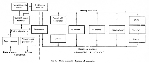
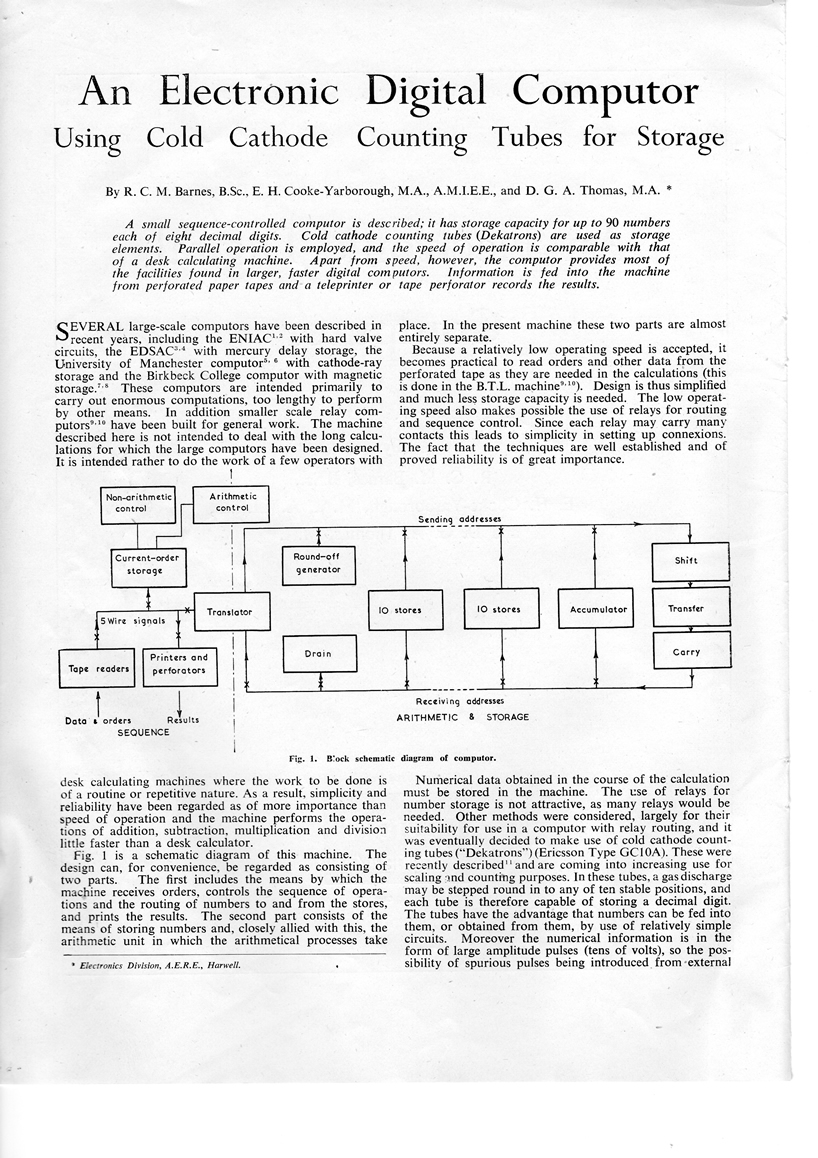
Fig 1 is a schematic diagram of this machine.
The design can, for convenience, be regarded as consisting of two parts,
the first includes the means by which the machine receives orders, controls
the sequence of operations and the routing of numbers to and from the stores,
and prints the results, the second part consists of the means of storing numbers and,
closely allied with this, the arithmetic unit in which the arithmetical processes take place.
In the present machine these two parts are almost entirely separate.
Because a relatively low operating speed is accepted, it becomes practical to read
orders and other data from the perforated tape as they are needed in the
calculations (this is done in the B.T.L.
machine).
Design is thus simplified and much less storage capacity is needed.
The low operating speed also makes possible the use of relays for routing and
sequence control.
Since each relay may carry many contacts this leads to simplicity in setting up connexions.
The fact that the techniques are well established and of proved reliability
is of great importance.
Numerical data obtained in the course of the calculation must be stored in the machine.
The use of relays for number storage is not attractive, as many relays would be needed.
Other methods were considered, largely for their suitability for use in a
computor with relay routing, and it was eventually decided to make use of
cold cathode counting tubes (“Dekatrons”).
These were recently described and are coming into increasing use for scaling
and counting purposes.
In these tubes, a gas discharge may be stepped round in to any of ten stable
positions, and each tube is therefore capable of storing a decimal digit.
The tubes have the advantage that numbers can be fed into them, or obtained
from them, by use of relatively simple circuits.
Moreover the numerical information is in the form of large amplitude pulses
(tens of volts), so the possibility of spurious pulses being introduced
from external sources is much reduced by comparison with other storage methods.
Use of these tubes permits the computor to work on a decimal, rather than a binary, basis.
This is convenient from several points of view; it is particularly
advantageous in a parallel computor, since the number of digits and
therefore the number of parallel arithmetical units, is considerably reduced.
Provided that the number of stores required is not too large, this method of storage
is thought to compare favourably with other methods on the basis of cost, size,
and power consumption per digit.
When the computor is fitted with its full storage capacity (90 eight-digit numbers,
equivalent to 2,700 binary digits) just over 800 tubes will be used.
The power consumption is about 150µA per tube at 370V.
From the fact that the tubes operate at this low current and from life tests to date,
tube life is expected to be many thousands of hours.
Each storage address consists of nine tubes, corresponding to eight digits with one
additional tube to indicate the sign.
The decimal point is regarded as being after the first figure of the number stored
whether this is a significant figure or zero, and the capacity n
of each store is +10 > n > -10.
Numbers are fed into stores and handled in the arithmetic unit as trains of pulses.
Negative numbers are handled as complements except on the punched tape and when
finally printed, when they appear as modulus and sign.
The basic process of addition (or subtraction by addition of the complements)
is carried out electronically in order to save the wear that would occur if
high-speed relays were used.
Multiplication and division is by a sequence of multiple additions (or subtractions),
with the operation of a relay circuit to shift the decimal point as each multiple
addition takes place.
No provision is made for reading of tables of functions and the low operating
speeds will often make it impracticable to calculate the required functions ab initio.
This must be regarded as a limitation of the present machine; it may eventually
be overcome by providing a special table reading attachment.
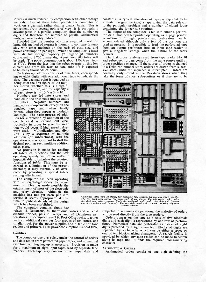
The computor has been operating with 20 eight-digit stores for some months.
This has made possible the establishment of most of the electronic and relay circuits.
Although the machine has not yet been put into service it seems appropriate at
this time to publish details of the design which has been established.
The computor contains about 380 relays, 18 Dekatrons, 80 thermionic valves and
40 cold cathode triodes, plus 28 relays and 90 Dekatrons per ten stores.
It occupies three 7 ft.
Post Office racks, together with an additional rack per four groups of ten stores,
one smaller rack for the power supplies and a table for tape readers and printers.
Total power consumption is about 1 kW.
Facilities
The computor operates solely under the control of orders and data fed in
from perforated paper tapes, and no manual switching or plugging up is necessary.
Provision is made for a maximum of eight input tapes read by separate tape readers.
Each tape may contain orders, input data, and constants.
A typical allocation of tapes is expected to be a master programme tape, a tape
giving the data relevant to the particular problem and a number of closed loops
containing the longer sub-routines.
The output of the computor is fed into either a perforator or a modified
teleprinter operating as a page printer.
A maximum of eight printers and perforators can be accommodated although
only a few of the positions are used at present.
It is possible to feed the perforated, tape from an output perforator into
an input tape reader to give a long-term storage when the nature of the work permits.
The first order is always read from tape reader No.
01 and subsequent orders come from the same source until an order specifies a change.
If the source of orders is changed to a Dekatron number store, orders
are drawn from successive stores until the sequence is interrupted.
Orders are normally only stored in the Dekatron stores when they take the form of
short sub-routines or if they are to be subjected to arithmetical operations;
the majority of orders will be read directly from the tape readers.
Orders appear on the tape as blocks of five (decimal) digits and each digit is
represented by one row of perforations.
Numerical data are perforated as blocks of eight digits preceded by a sign character.
Blocks of digits are separated by a character which can be either a space or
one of ten block-marking characters.
A search facility is provided by which any tape reader can be made to search
along its tape until it finds the required block-marking character.
ARITHMETICAL ORDERS
Arithmetical orders consist of one digit defining the arithmetical
operation to be performed, a sending address (two digits) and a receiving
address (two digits).
The sending address may be a Dekatron store, the accumulator, a tape reader,
or the rounding-off circuit The receiving address may be a store, the accumulator,
a printer or perforator, or a drain for unwanted numbers.
Seven operation digits have been allocated as follows:
(1) Add the contents of the sending address into the receiving address, and leave
the contents of the sending address unchanged.
(2) Add the contents of the sending address into the receiving address and clear
the sending address.
(3) Subtract and do not clear the sending address.
(4) Subtract and clear the sending address.
(5) Multiply the contents of the sending address by the contents of
the “receiving address” clearing the latter, and add the
product into the accumulator.
(6) Divide the contents of the accumulator by the contents of the sending address,
form the quotient in the receiving address and leave the remainder
in the accumulator.
(7) Add the positive modulus of the contents of the sending address into
the receiving address.
The sending and receiving addresses must not lie in the same group of
ten stores; in the case of multiplication and division they must not refer
to an input or output organ.
It should be noticed that addition and subtraction do not require the use of
an accumulator, because the result of a direct transfer of the contents of
a store into an already occupied store is to form a sum.
In this operation the original number in the latter store is lost unless it
is also stored elsewhere.
The accumulator is only required as a third address, of length 15 digits,
for the purpose of multiplication and division, but it can be used exactly
as a normal store at other times.
NON-ARITHMETICAL ORDERS
In non-arithmetical orders the operation digit is 0 and is followed
by two further digits calling for a change of the address from which orders
are obtained, search for a block-marking character, examination of the sign
of the number in a specified address, or selection of the layout of the printed result.
The last two digits specify the address concerned.
The sign examination facility allows the future action of the computor to be
controlled by the state reached by the calculation.
Any store can be examined for the presence of either a positive or a negative sign.
If the sign looked for is found, an affirmative relay is locked in and any
subsequent conditional orders (see below) are performed; otherwise they are ignored.
The order calling for a change in the order source can be made conditional
or unconditional; if conditional it is only performed if the previous sign
examination has given an affirmative result.
This allows a new set of orders to be brought in when the previous set has
brought the calculations to a desired stage.
The order requiring a search for a block-marking character causes all the
information to be ignored which lies between the present position on the
tape and the specified character.
This can again be made conditional on the result of the previous sign examination.
Facilities are provided for the tape to be searched in either the forward
or the reverse direction, although the tape readers at present available only
allow search in the forward direction.
The ability to search in reverse will allow sections of the order tape to
be used repetitively without necessitating a closed loop of tape,
The print layout is variable to a limited extent.
There are ten layouts available for printing each eight digit number,
for instance one such layout might consist of the eight digits followed by spaces,
and another the eight digits followed by line-feed and carriage return.
An order is required to define which layout is to be used.
and it stays in force until replaced by another print layout order.
Arithmetical Operations
ADDITION AND SUBTRACTION WITH SINGLE TUBES
As has already been stated, addition is the fundamental operation.
Subtraction is effected by adding the complement, and multiplication (or division)
by a sequence of multiple additions (or subtractions).
The circuits used for adding a number from one store into another therefore form
the basis of the arithmetic unit, and are described in detail.
Numerical information is handled in the form of trains of up to nine pulses.
Each train represents one decimal digit, and as parallel operation is employed
there is a separate channel to handle each digit For normal arithmetical
operations the pulses are routed, through a transfer unit, from one store
to another, or to the “accumulator”.
When a digit is being fed from a store to a printer a translator unit is
used to convert the train of pubes into a form suitable for operating
the relays which control the printer.
The same translator is used when reading numerical information into the
computor to convert digits stored on relays into trains of pulses.
It is connected to the transfer units in exactly the same way as a store
but only handles one digit at a time.
It is first necessary to consider the mode of operation of the gas-filled tubes
(Dekatrons) which form the basis of the storage system.
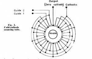
The arrangement of a Dekatron is shown diagrammatically in Fig. 2.
Ten cathodes are equally disposed round a central anode and all but one are connected together.
Between adjacent cathodes there are two guide electrodes, and these are
connected together in the way shown.
Normally the zero cathode is taken through a resistor to earth or to a
small bias potential, and the remaining cathodes are earthed.
The guides rest at +60V and the anode is connected through a resistance of 1M to + 370V.
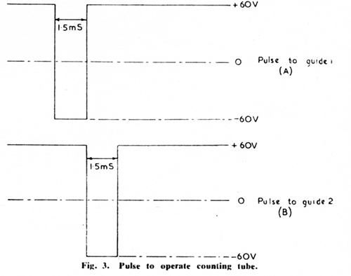
Pulses of the form shown in Fig. 3 are applied to the guide electrodes
to move the discharge from one cathode to the next.
During the first pulse the discharge moves to the next guide 1 electrode.
At the end of the first pulse the discharge moves on to guide 2, which is
then more negative than the previous cathode.
At the end of the second pulse, the discharge moves to the nearest cathode
and has advanced one step.
It is not necessary for the two guide pulses to overlap, but it is important
that any time interval between the end of the first pulse and the start of
the second should not be comparable with the de-ionization time of the Dekatron tube.
A small overlap has been provided as a precaution against possible failures.
If pulses are applied to one guide only, the discharge returns to the same
cathode after each pulse.
The method used to pass a digit into the tube is to apply n pairs of pulses
of the type shown in Fig.3 to the guide electrodes.
The discharge will then advance by n steps, and if the discharge starts from
zero, or output cathode, it will move to cathode n.
To read a digit out of a storage tube, a train of ten pairs of pulses may
be applied to the tube, causing the discharge to circulate and return to its starting point.
A pulse is produced as the discharge passes the zero or output cathode.
and the number of pulses of the train of 10 which occur after the output
pulse is an indication of the digit stored on the tube.
Further, the number of pulses preceding the output cathode pulse is the
complement on 10 of the digit stored in the tube.
The function of the transfer unit is to accept the output cathode pulse
from the Dekatron tube from which the digit is being taken (“sending tube”),
and from it to derive the pulses representing the digit and complement,
either of which is passed to the receiving tube.
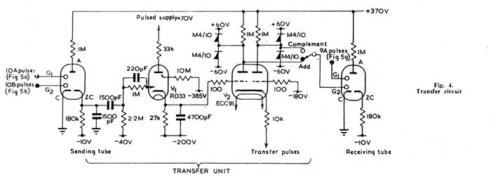
Fig. 4 is a circuit of one transfer unit, and Fig. 5 shows the waveforms
appearing when the digit 3 is transferred.
When an addition is to be performed, a relay is energized in a pulse generator
unit, which, after a short delay to allow any transients from the relay circuits
to die away, produces a train of ten pulses as shown in Fig. 5(a) and 5(b).
These pulses are applied to the sending tube, which therefore steps round by
one complete revolution.
When the discharge arrives at the output cathode, a waveform of the form shown
in Fig, 5(c) is produced, and this is used to trigger the cold cathode triode V1.
The cathode potential of V1 rises from -200 to -160, and the
left half of V2 conducts.
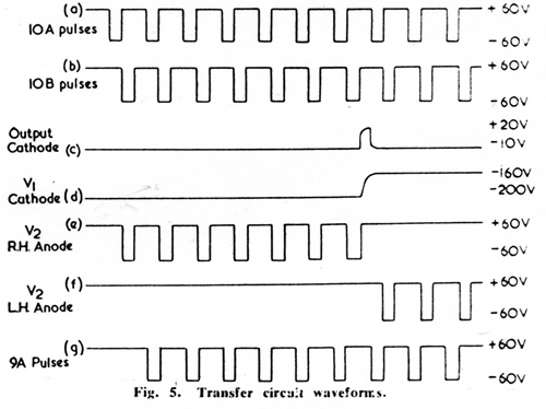
Pulses are applied to the cathode of V2 synchronously with those shown
in Fig. 5(b), but at a different D.C. level, and, prior to V1
being triggered, they produce negative pulses
at the right anode of V2 (Fig. 5(e)).
When V1 is triggered the pulses appear at the left anode (Fig. 5(f)).
It will be seen that the left anode delivers the digit, and the right
anode the complement on 10.
These pulses are suitable for direct connexion to one guide of the receiving tube.
Since, for the purposes of subtraction, the complement on 9 is required,
it is arrange that only 9 pulses are applied to the guide on the receiving tube
(Fig. 5(g)) so that the first pulse in the train shown in Fig. 5(e)
is ineffective in moving the discharge.
If the sending tube is to be cleared to zero during the transfer, the
complement output of the transfer unit is connected to one of the
sending tube guides in place of the train of ten pulses.
This method of clearing stores is also used when the machine is first
switched on since the Dekatron tubes may light in any position.
When the transfer operation is carried out purely to clear a store no
receiving tubes are connected, but a dummy circuit
(the drain address “00”) is connected to simulate a
receiving address, in order to satisfy the checking
arrangements in the address selecting circuits.
To extinguish V1 and minimize the chance of spurious
triggering taking place, H.T.
is removed from its anode from the end of each operation until the start of the next.
MULTI-DIGIT ADDITION AND SUBTRACTION
As well as the transfer circuits described above, circuits are needed
to perform carryover, when required, from each digit into the next most significant.
The “carry” circuits consist of a cold cathode valve which is triggered when
the receiving store reaches or passes zero.
This valve remains conducting until the end of the train of transfer pulses,
when a second valve performs the carry over and the first is extinguished.
A transfer and a carry circuit is required for each digit.
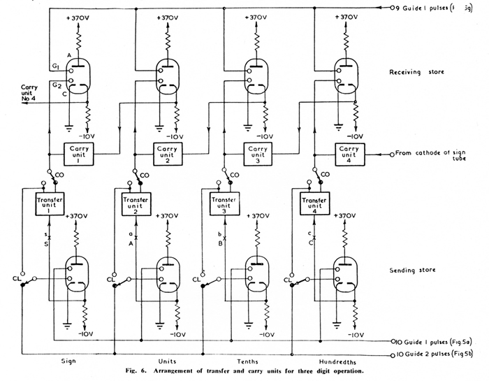
Fig.
6 is a diagram showing the connexions for a four-digit store with carry circuits,
11 will be noted that the most significant tube has a carry circuit, and
carryover is made into the least significant tube.
This carry circuit plays no part in handling positive numbers, but is necessary
to handle complements.
When the complement of a multi-digit number is found, the complement on 10 is
required for the least significant digit and the complement on 9 for all the other digits.
It has already been explained that in this machine the complement on 9 is found
for all digits; there is no simple means of checking electrically which tube
in a store carries the least significant figure.
Carryover from the most significant tube to the least significant corrects this,
as can readily be demonstrated, and enables the complement on 9 to be used in
every case, whether in finding the complement of a number or finding the number
from its complement.
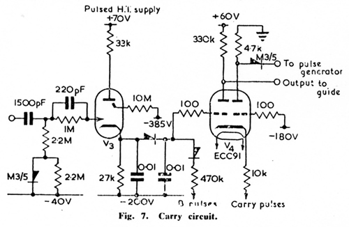
The arrangement of the carry circuit is shown in Fig.
7.
The pulse generator continues to produce the pulses shown in Fig.
5(g) (applied to receiving tubes) after the main train of 9 is completed.
It also provides pulses for application to V4 cathode similar
to those applied to the cathode of V2 in the transfer unit
but on a separate wire and beginning immediately after the train of transfer
pulses is completed, If the receiving tube connected to V3
reaches or passes zero, V3 is triggered, and the potential
of the left grid of V4 is raised.
When a pulse is applied to V4 cathode it then appears at the
left anode and is applied to the guide of the next most significant receiving tube.
A pulse is applied simultaneously to the anode of V3, and
extinguishes the discharge, Subsequent pulses applied to V4
cathode appear at the right anode of V4.
The simultaneous appearance of pulses at the right-hand anodes of all carry
units indicates that the carry operation is complete.
This is arranged to stop the pulse generator and send a “finish”
signal to the relay sequence control circuits, which then proceed with the next step.
Means must be provided on each store to show whether the content is a positive
number, or a complement (representing a negative number).
This could be done by some device (for example a cold cathode trigger valve)
having two stable states, but for circuit convenience an additional Dekatron
has been used in each store.
An additional transfer and carry unit is used, wired so that the sign tube
receives the carry over from the most significant tube.
Carry over from the sign tube is passed into the least significant tube.
For positive numbers the sign tube is at zero, and for complements at 9.
A double triode is connected to the output cathode of the sign tube, and this
operates two relays corresponding to + and -.
The contacts of these relays give sign information required when multiplying,
dividing or printing.
It is also arranged that a warning is given when this sign inspection circuit
is not connected to any tube, perhaps as a result of faulty address selection.
MULTIPLICATION AND DIVISION
Division necessitates the use of a special store (the accumulator)
having 15 digits, since when an 8-digit quotient is to be obtained with an
8-digit divisor, there are cases where difficulties would arise if a
15-digit dividend were not provided.
An accumulator of more than eight digits also reduces errors in rounding off the
product of multiplication if products are repeatedly summed in the accumulator.
A further advantage of a long accumulator is that the remainder after division is
available for use if required.
In both multiplication and division one storage address is used as the sending store,
the accumulator is connected to the output of the transfer units, and a second
storage address is used in a special way, to be described, and is referred to as a register.
The contents of these stores are shown in Table 1.
Circuits are provided to inspect the sign of each of these stores and immediately
the addresses have been selected relays connected to these circuits ensure that
the arithmetical operations to be performed will result in a product or quotient
of the correct sign.
| |
TABLE 1 |
|
| |
|
|
| |
MULTIPLICATION |
DIVISION |
| SENDING STORE |
MULTIPLICAND |
DIVISOR |
| ACCUMULATOR |
PRODUCT |
DIVIDEND |
| REGISTER |
MULTIPLIER |
QUOTIENT |
Where the multiplier is positive, the multiplicand is added into the accumulator
N1 times where N1 is the number stored in
the most significant tube of the register (multiplier).
A shift to the right is now introduced by the relay shift circuit (i.e., in Fig. 6,
point A is connected to b and B to c, points S and a being connected to s), and
the multiplicand added into the accumulator N2 times, where
N2 is the number stored in the second tube of the register.
This process of multiple additions alternating with operation of the shift unit
continues until the whole of the multiplier is dealt with, In order to perform
the correct number of additions, the tube in the register containing the digit
of the multiplier being considered is moved back one step (for convenience it
is actually moved on nine steps without carry over) for each single addition.
The pulse generator is arranged to give the finish signal calling
for the next operation when the appropriate digit of the register
has reached zero and carryover is complete.
When the multiplier is a complement, a similar procedure is carried out
with a few modifications.
Multiple subtractions are required, and the register tube is moved forward
one step for each subtraction.
Since the complement of 0 is 9, it follows that transfers should stop when
the register tube reaches 9, As the pulse generator allows transfers to
continue until the tube reaches 0, one too many will be performed by the
time the finish signal is given, and it is necessary to make a single
addition to correct for this.
The sequence then is multiple subtraction, single addition, operation of shift.
These sequences are controlled by relays in the sequence controlling and
routing section of the machine.
It is, of course, only necessary to give the order “multiply”;
the precise sequence required is selected before the operation starts by
a relay circuit dependent on the sign of the contents of the selected addresses.
Division is performed by a sequence of the same form, i.e., multiple transfer,
single transfer, operation of the shift; the quotient is built up digit by digit
in the register by moving the discharge one step forward or backward in the
register for each transfer.
For a divisor and dividend of the same sign, the divisor is subtracted from
the dividend and the register moved forward until the sign of the dividend
changes, when the pulse generator gives the finish signal.
At this point one subtraction too many has been performed, and this is
corrected by making one addition and moving the register back one step.
When the divisor and dividend are of opposite sign, the multiple transfers
are additions, with the register being moved back step by step and the
single transfer is a subtraction.
In this case it is not necessary to move on the register during the single
transfer, since the fact that it has started from 0 rather than 9,
the correct starting point for a complement means that the necessary
correction has already been made.
ROUNDING OFF
After multiplication or division, some form of rounding off is
normally needed to avoid a systematic error due to the omission of digits
less significant than the least significant held in the stores.
In multiplication, rounding off is most conveniently done when the product
is transferred from the 15-digit accumulator to an 8-digit store.
A method commonly employed is to add five to the most significant of
the digits which are omitted in this process; carryover then adds one
to the least significant figure retained if the omitted figure was 5 or over.
The maximum error in the last digit is ±0.5, and the average error is zero.
This process would have proved inconvenient in the present machine, partly
because it would involve the generation of a special train of 5 pulses,
but also because in the case of division, the quotient is built up in an
8-digit store, and without much extra complication a 9th digit
is not available to be rounded off.
Accordingly the cruder method of adding 1 or 0 at random to the 8th
figure of the product or quotient has been adopted.
The maximum error in this digit is now ±1.
and the average error is zero, The probable error after rounding off in this way
is about twice that to be expected from the more conventional process.
This error is not considered serious.
A more important point is that the random nature of the result makes difficult
the precise checking of the machine by repeating a solution in which rounding
off had taken place.
To minimize systematic errors the selection of 0 or I for rounding off must
be as nearly random as possible.
The method adopted is relatively simple.
A master oscillator in the pulse generator produces continuously the pulses
which are subsequently routed to perform the transfer and carry operations.
Pulses from this oscillator are fed continuously to a scale-of-two circuit,
a pair of cold cathode triodes which conduct alternately.
When rounding off into any address the state of the scale-of-two circuit at the
beginning of the transfer period determines whether 0 or 1 is transferred in the last digit.
The relation between the state of the scale of two at the beginning of one round
off operation and that at the beginning of the previous round off thus depends
upon whether the number of pulses occurring in the intervening period is odd or even.
These pulses are spaced a few milliseconds apart whereas the interval between
successive round off operations is several (usually very many) seconds.
The exact length of this interval is affected by many uncertainties, such as the
operating times of the tape readers and printers and many relays, These may
confidently be expected to produce unpredictable variations in the interval
amounting to very many milliseconds.
Experiments so far carried out show no significant correlation between the zeros
and ones produced by repeated round off operations.
The Translator Unit
The function of the translator unit is to convert the information obtained
via a relay circuit from a punched paper tape into a form suitable for operating
the transfer units in the computor and vice versa.
The translator is brought into circuit in the same way as any storage address and
no alteration is needed to the transfer unit to accommodate it.
The basis of the unit is a special Dekatron in which the cathodes are all brought
out separately.
For this purpose a 10-cathode tube would be suitable, but the tube available has
11 cathodes (GSIIA) and this has been used.
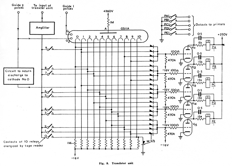
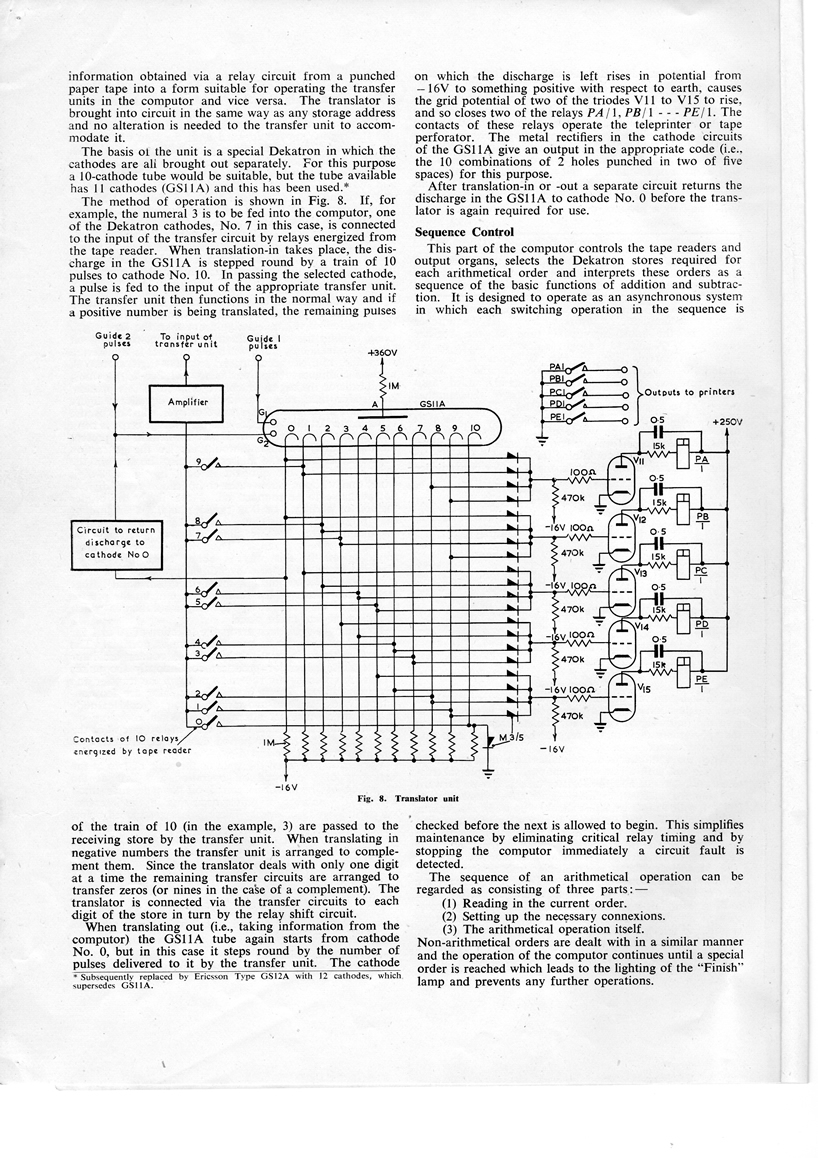
The method of operation is shown in Fig.8.
If, for example, the number 3 is to be fed into the computor,
one of the Dekatron cathodes, No.7 in this case is connected
to the input of the transfer circuit by relays energized from the tape reader.
When translation-in takes place, the discharge in the GSIIA
is stepped round by a train of 10 pulses to cathode No. 10.
In passing the selected cathode.
a pulse is fed to the input of the appropriate transfer unit.
The transfer unit then functions in the normal way and if
a positive number is being translated, the remaining
pulses of the train of to (in the example, 3) are passed
to the receiving store by the transfer unit.
When translating in negative numbers the transfer unit is
arranged to complement them.
Since the translator deals with only one digit at a time the
remaining transfer circuits are arranged to transfer
zeros (or nines in the case of a complement).
The translator is connected via the transfer circuits to each
digit of the store in turn by the relay shift circuit.
When translating out (i.e. taking information from the computor)
the GSIIA tube again starts from cathode No.
0, but in this case it steps round by the number of pulses delivered
to it by the transfer unit.
The cathode on which the discharge is left rises in potential
from -16V to something positive with respect to earth, causes the grid
potential of two of the triodes VII to V15 to rise, and so closes two
of the relays PA/1, PB/1 - - - PE/1.
The contacts of these relays operate the teleprinter or tape perforator.
The metal rectifiers in the cathode circuits of the GSIIA
give an output in the appropriate code (i.e. the 10 combinations of
2 holes punched in two of five spaces) for this purpose.
After translation-in or -out a separate circuit returns the
discharge in the GSIIA to cathode No, 0 before the translator
is again required for use.
Sequence Control
This part of the computor controls the tape readers and
output organs, selects the Dekatron stores required for each
arithmetical order and interprets these orders as a sequence
of the basic functions of addition and subtraction.
It is designed to operate as an asynchronous system in which each
switching operation in the sequence is checked before the next is allowed to begin.
This simplifies maintenance by eliminating critical relay timing and
by stopping the computor immediately a circuit fault is detected.
The sequence of an arithmetical operation can be regarded as consisting of three parts:
(1) Reading in the current order.
(2) Setting up the necessary connexions.
(3) The arithmetical operation itself.
Non-arithmetical orders are dealt with in a similar manner and the
operation of the computor continues until a special order is reached
which leads to the lighting of the “Finish” lamp and prevents any further operations.
READING IN THE CURRENT ORDER
Each order is transferred, digit by digit, from the perforated
tape or Dekatron store into the relay order storage circuit and is
then interpreted as a sequence of additions and subtractions.
The address from which the order is obtained has been derived from
an earlier order calling for a change of order source.
This address is stored on a group of relays which mark out the two
digits of the order source address.
The “tens” digit energizes a relay connecting a group of ten addresses
as the sending store and the “units” digit selects the individual store in this group.
The reading-in sequence begins when it has been proved that the correct
tens and units relays have operated.
If the order source is a tape reader the sequence will consist of six cycles.
The space or block-marking character is read during the first cycle
and the order digits during the remaining five cycles.
At the beginning of each cycle the appropriate relay storage group
is connected to the five wire output of the tape readers.
The contacts of each tape reader correspond with the pattern of
holes on the tape, and they operate the equivalent combination
of five relays in the storage group to which they have been connected.
The relay storage group into which the space or block-marking
character should be routed will only allow the next cycle to commence
if it receives a particular combination of one hole out of five
(the space combination) or any combination of three holes (the block-marking characters).
The five storage groups into which the order digits are fed
will only allow the next cycle to commence if each receives
one of the ten combinations of two holes.
If the tape reader moves the tape forward more than one row
before reading the next character, or fails to move the tape,
a digit storage group will be offered the space code or vice versa.
Furthermore, any erratic operation of the reading contacts is
unlikely to distort a two-hole code into another two hole
code, so that any faulty operation of the tape reader is almost certain to be detected.
SETTING UP THE CONNEXIONS
The source from which the current order has been read
and the relay storage group are now disconnected, leaving the
order stored on the relays.
If this order requires an arithmetical operation the sending and
receiving addresses are selected and connected to the input and
output of the transfer system in the following way.
The Dekatron stores are built in units each containing ten stores of
eight digits and sign.
These units are a convenient size and suit the decimal address code.
Each group of ten stores has switching relays which connect it either
to the input or the output of the transfer systems.
These are the sending and receiving “tens” relays.
When a “tens” relay is energized the Guide 2 electrodes of all the sign
storage Dekatrons in the group are connected to the sign input or output
lead of the transfer system, all the Guide 2 electrodes of the
1st digits to the 1st digit lead, and so on.
The individual store in the group is selected by one of ten switching relays
(the “units” relays) which connects Guide 1 pulses to all the
Dekatrons of one address.
Thus although all the 90 Dekatrons in the group of 10 addresses receive
Guide 2 pulses, only those of the selected address receive pulses
on both guides and the position of the discharge can change only in this one address.
The two sets of “tens” and “units” relays which
bring the sending and receiving addresses into action are selected and
checked by four groups of address storage relays.
A fifth group stores the operation to be performed and, provided that the
addresses selected are compatible with the operation demanded, sets up
the arithmetic control relay circuits.
As a further guard that the sending and receiving addresses are connected
correctly the arithmetic sequence cannot start until the signs of both
addresses and of the accumulator have been identified.
THE ARITHMETIC OPERATION
When the selection of function and addresses is complete arithmetical
sequence begins.
It occupies it variable number of cycles, only one for addition or subtraction,
nine for multiplication, ten for division, 11 for reading in a number from
the tape and up to 19 for printing a number in a maximum length print layout.
For addition or subtraction the single cycle has two steps: setting the shift
circuit to the straight-through condition and carrying out a single transfer.
For division of a positive dividend by a positive divisor each cycle has three
steps: setting the shift to successive positions, carrying out a multiple
subtraction until the sign of the accumulator changes, and carrying out a single addition.
The completion of each step is checked before the next can begin.
When the arithmetic sequence has produced the full number of cycles required
for the particular operation the address relays are released, the stored
order is cleared down and the next order reading sequence begins.
PRINTING OUT
If the current order selects the printer as the receiving address
the translator is connected to the output of the transfer system and the printer is connected to the five wire output of the translator.
A previous order will have specified the print layout which is to be adopted.
Each cycle of the arithmetical sequence then consists of three steps.
The first sets the shift to route each digit in turn to the input of the
translator (which accepts only one digit at a time).
At the same time the translator is recycled to zero.
During the first step there may alternatively be connected to the printer
the contacts of one of a number of relays which mark out non-digital
characters such as space, line feed and carriage return.
The second step is a single addition or subtraction.
If a non-digital character has been selected by the first step this transfer is not required.
The teleprinter with page printing attachment has been modified so that
five-wire signals operate magnets controlling the five combs of the combination head.
The third step of each cycle sets the combination head of the teleprinter by operating
these magnets from the output of the translator or a character relay,
checks the position of the combs, and prints a character.
CONCLUSION
It is believed that the computor described above will meet a real need in
the computing field.
It is particularly suited for cases in which the same calculation must be performed
many times on a variety of numerical data, Its use is expected to be an economical
proposition in many cases when the cost of a large fast computor would not be justified.
Acknowledgement
The authors have received much helpful advice from Dr.
J.
Howlett, and during the early stages of the work they benefited by a discussion with
Professor D.R. Hartree.
The work was carried out as part of the programme of the Electronics Division
at A.E.R.E and is published by permission of the Director, A.E.R.E.
|
